
Postal Machine (1897)
U.S. Patent No. 585,076, granted on June 22, 1897, to William Barry, describes a high-speed, automated postmarking and stamp-canceling machine engineered to handle heavy volumes of mail. William Barry, residing in Syracuse, Onondaga County, New York, developed this system to dramatically improve mechanical reliability and throughput in postal processing facilities.
This invention solved a critical operational bottleneck in late 19th-century post offices: existing canceling machines were delicate, subject to high friction and frequent breakdowns, and prone to “skipping” or feeding multiple envelopes simultaneously. Barry created an accessible, durable machine capable of feeding, postmarking, canceling, and stacking thousands of letters continuously without constant mechanical adjustment.
The Innovation: Synchronized Dual-Action Separation & Feeding
Prior postal machines struggled with envelope friction, variations in paper thickness, and envelopes sticking together due to moisture. Barry’s breakthrough combined a needle-pointed reciprocating feeder with a secondary rotary friction roller and a multi-stage spring separator.
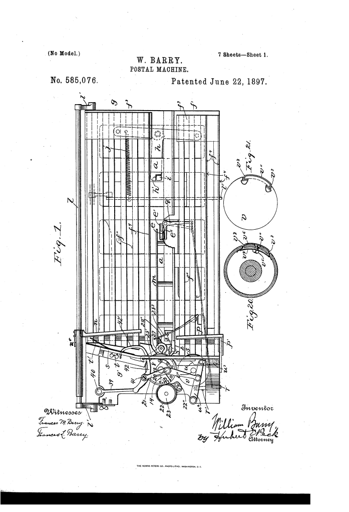
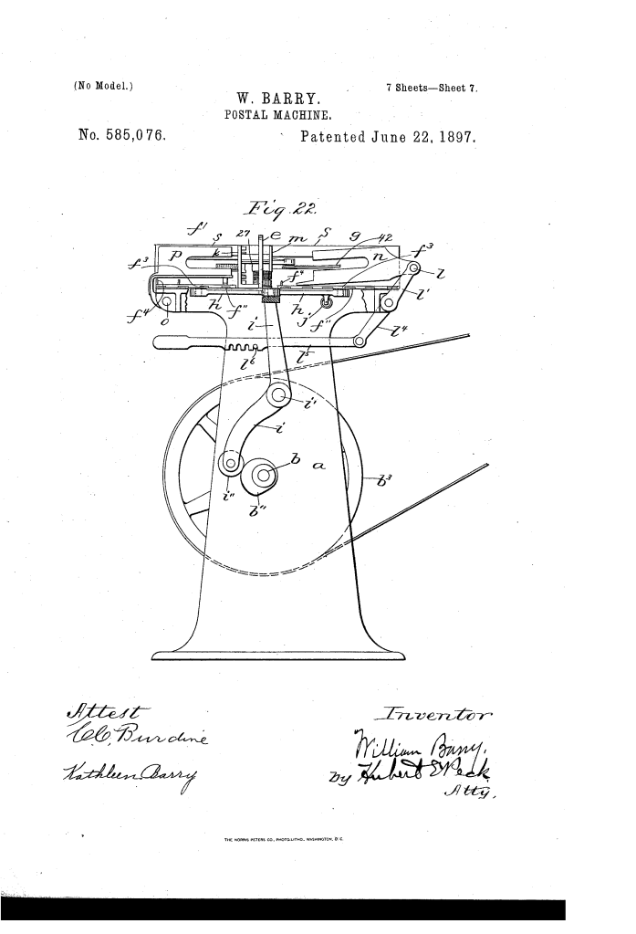
+-----------------------------------------------------------+| FEEDWAY (f) || Letters moved forward on reciprocating floor bars |+-----------------------------------------------------------+ | v+-----------------------------------------------------------+| SEPARATOR & FEEDING STAGE || * Auxiliary Roller (v): Starts & aligns envelope || * Needle Feeder (u): Positive grip on front envelope || * Separator Fingers (4, 5, 6): Restrain trailing mail |+-----------------------------------------------------------+ | v+-----------------------------------------------------------+| PRINTING & IMPRESSION COUPLE || * Printing Roll (8): Segmental canceler & date type || * Impression Roll (27): Rockable platen on swing arm |+-----------------------------------------------------------+ | v+-----------------------------------------------------------+| RECEIVING-WAY (g) || * J-Shaped Pusher (42): Stacks postmarked letters || * Automatic Stop: Trips clutch when feedway empties |+-----------------------------------------------------------+
Why This Feeding System?
- Positive Separation: The primary feeder uses parallel rows of fine needle points held in a soldered block to grip the front face of each envelope positively without slipping.
- Inertia Relief: The auxiliary friction roller (v) engages the letter at an intermediate point, breaking resting friction and pushing misaligned mail flush against the guide before the main feeder stroke.
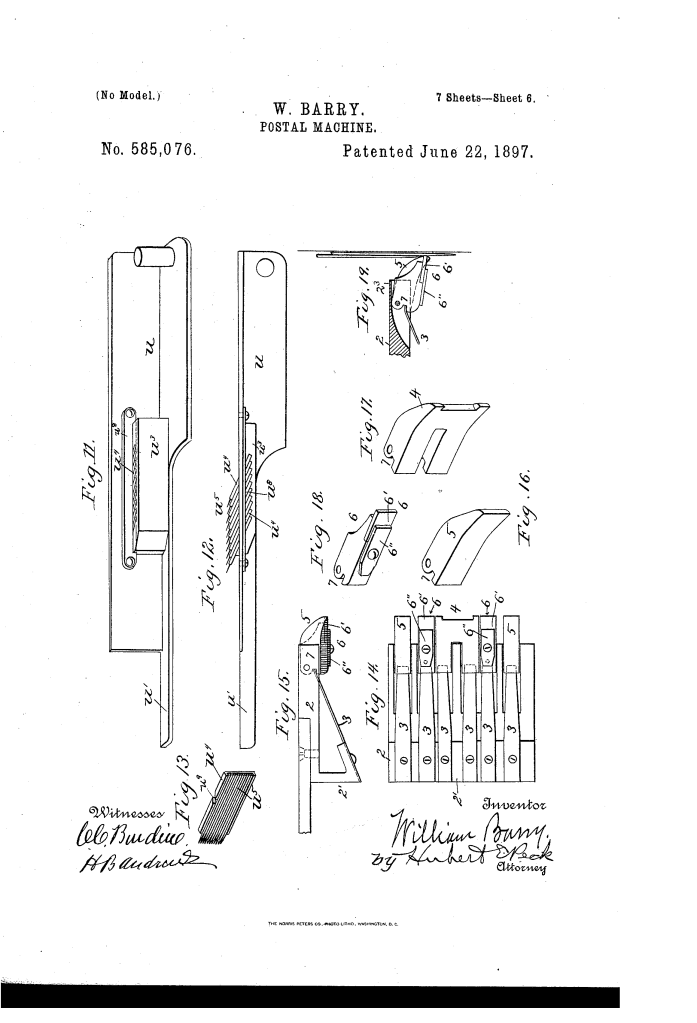
- Double-Feed Prevention: A vertical array of spring-loaded separator fingers balances rounded pressure pads (which prevent edge crumpling) with sharp-edged reversible metal blades that snag and restrain any trailing envelopes.
Key Mechanical Components
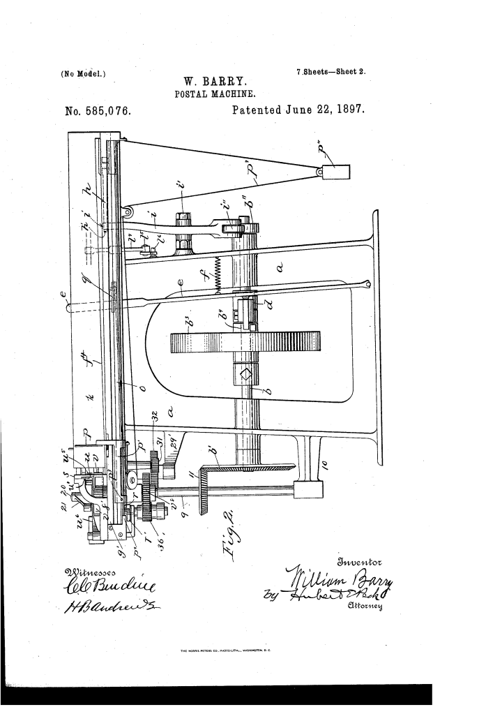
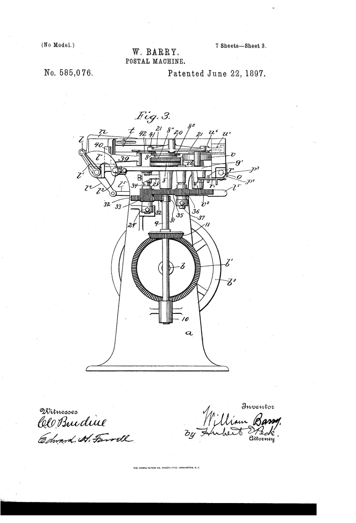
The machine integrates feeding, printing, and stacking into a single continuous driveline driven by an eccentric pitman arm and cam system:
| Component | Function |
| Reciprocating Letter-Way Floors (f’, g) | Oppositely reciprocating parallel floor bars with raised side edges; uses a slow forward stroke to advance mail and a rapid return stroke to slip underneath without back-drag. |
| Reciprocating Needle Feeder (u, u^3) | Sits on a sliding carrier operated by the printing roll; features a block of fine, inclined needles that grab each envelope and pull it past the discharge gate. |
| Auxiliary Feed Roll (v) | A timed rotating roller with an adjustable friction segment (v^1) that overcomes letter inertia and aligns unevenly placed envelopes against the guide wall. |
| Multi-Stage Separator Fingers (4, 5, 6) | A vertical bank of spring-actuated fingers; convex fingers (4, 5) press the letter flat, while square-edged, 4-way reversible plates on fingers (6) hold back behind-lying mail. |
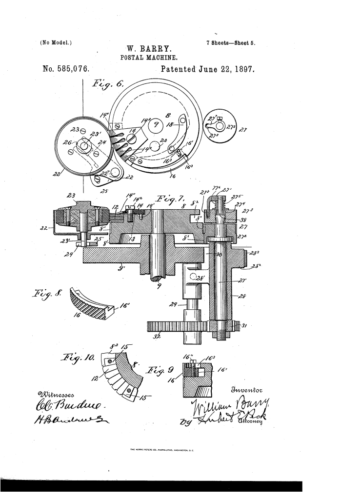
| Segmented Printing Roll (8) | Features a lower smooth clearance zone, a milled traction band, removable date/time type slots, and an adjustable, swingable stamp-canceling die (16). |
| Rockable Impression Roll (27) | Platen roll mounted on an offset swinging arm (28′) with a rockable inner bushing (27′) that self-levels against thick, thin, or uneven letters. |
| J-Shaped Stacker Pusher (42) | Driven eccentrically in timed sequence with the feeder; scoops newly postmarked letters sideways and rearward into a neat stack. |
| Automatic Clutch Trip (q, r) | A follower-actuated trip lever that disengages the drive pulley clutch and halts the machine the moment the final letter leaves the feedway. |
Step-by-Step Operation of the Machine
[1. Loading Mail] │ (Letters loaded in bulk into feedway f against follower p) ▼[2. Bottom Feed & Alignment] │ (Reciprocating bars advance batch; roller v aligns lead envelope) ▼[3. Needle Grip & Separation] │ (Needle block u grabs front letter; fingers 6 hold back trailing mail) ▼[4. Printing & Impression] │ (Envelope passes between rolls 8 & 27; canceler 16 and date type strike face) ▼[5. Discharge & Stacking] │ (J-shaped pusher 42 sweeps letter into receiving-way g against follower n) ▼[6. Automatic Shutdown] (Follower hits trip lever r; clutch d disengages drive shaft b)
- Loading: The operator places several thousand faced envelopes into the elongated feedway (f), held upright by the weighted follower (p).
- Batch Advance: As drive shaft b rotates, cam b’ and lever h reciprocate the floor bars, steadily advancing the mass of mail toward the front wall (s).
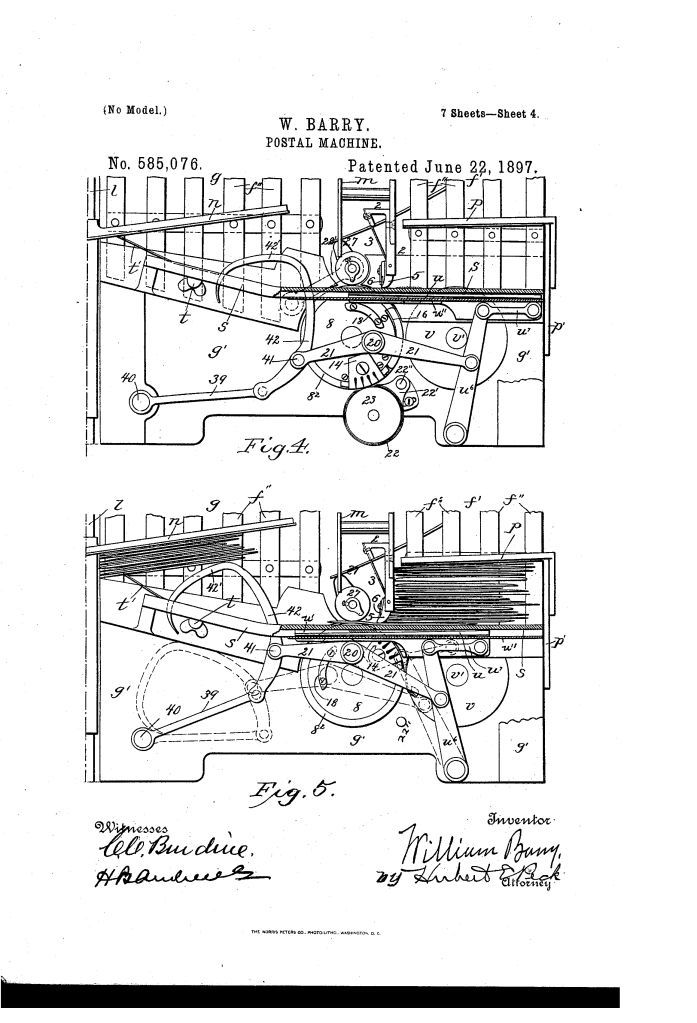
- Primary & Auxiliary Feeding: Auxiliary roller v rotates, contacting the body of the lead letter to break its inertia and align its edge. Simultaneously, top cam 18 forces the needle feeder (u) inward to sink its needle points into the lead letter.
- Single-Letter Gate: The feeder draws the letter across the discharge throat. Broad convex fingers (4, 5) hold the envelope flat against wall s, while reversible square plates on fingers (6) strip away any double-fed envelopes.
- Marking & Impression: The envelope enters the printing couple. The rockable impression platen (27) yields outward along an arc to absorb package thickness while holding the paper firmly against the inking type (12) and canceling block (16).
- Stacking & Ejection: Pitman 21 drives the J-shaped pusher (42), sweeping the processed letter into the receiving-way (g) and compacting it against the tension-controlled receiving follower (n).
- Auto-Stop: When the last envelope clears the feedway, follower slide p’ contacts trip lever r, pushing elbow lever q to release clutch handle e, instantly stopping the machine.
Operational Versatility & Durability Features
- Incoming vs. Outgoing Mail Modes: The stamp-canceling block (16) is mounted on an internal pivot. Tightening or loosening clamping screw 16′ allows the operator to retract the canceling bars within the roll radius for incoming mail (backstamping place and arrival date only) or extend them flush for outgoing mail (canceling postage and applying circular postmark).
- Self-Leveling Platen: The impression roll’s central sleeve (27′) rocks freely on an upward-facing shoulder (38) of shaft 27′, maintaining a perfectly parallel impression surface across envelopes containing folded inserts, uneven enclosures, or bulky contents.
- 4-Way Reversible Wear Plates: The high-wear separator plates (6′) are cut with square edges on both ends. When an edge dulls from paper friction, postal mechanics can unclamp, rotate, or flip the plate to expose four independent working edges before replacement is required.
Summary of Claims
The patent explicitly claims:
- The combination of reciprocating feedway and receiving-way floor beds driven in opposite directions by an oscillating, three-armed horizontal lever and single cam driveline.
- A dual feeding mechanism combining a reciprocating needle-point biting block with a coordinated auxiliary rotary friction roller.
- A multi-finger separator incorporating rounded envelope-pressing faces paired with sharp-edged, selectively reversible metal plates to prevent multiple feeds.
- A self-adjusting impression roll mounted on a rockable internal shoulder and supported by a diagonal swinging arm pivoted forward of the printing plane.
- An automatic stop-motion assembly linking a weighted feedway follower to a spring-actuated sliding clutch disconnect.
