
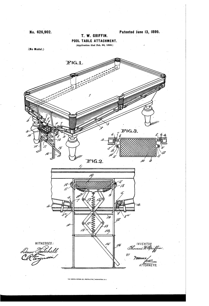
Pool Table Attachment (1899)
U.S. Patent No. 626,902, granted on June 13, 1899, to Thomas Walter Griffin, describes a mechanical ball-return and elevated retrieval system designed for pool and billiard tables. Griffin, an inventor based in Milford, Connecticut, assigned the patent jointly to himself and Henry C. Goodwin.
This invention solved a universal physical annoyance in the game of billiards: the tedious task of walking entirely around the perimeter of the table to retrieve pocketed balls one by one from separate net pockets, followed by stooping and bending over to gather them up for the next rack. Griffin designed an integrated raceway and foot-lever-operated lift that brought all sunk balls directly to the player at table height.
The Innovation: The Foot-Operated Elevating Receiver
While rudimentary ball troughs existed, they dumped balls into a low basin near the floor, which still forced players to stoop. Griffin’s core mechanical breakthrough was a vertically traveling ball receiver combined with an automatic gate-tripping sequence:
- External Gravity RacewaysDual-wire tracks (1) connected by transverse strips (3) extend along the sides of the table frame on a continuous downward incline toward the head of the table.The side and corner pockets feed directly into these raceways, routing all pocketed balls down into short transverse sections (4) across the head rail.Because the raceways run along the outside of the table frame rather than being buried within the cabinet, lodged balls are easily freed, and tracks can be wiped clear of chalk dust and debris without taking the table apart.
- Toggle-Link Foot LiftA receiving tray (10) framed by rigid bars (9) rides vertically on twin tubular guides (12) mounted between the floor and the upper rail of the table.A system of toggle links (13) connects the bottom frame bar (12) to a stationary cross-bar (14) anchored to the guides.A player depresses a foot lever (15) extending outward from the lower toggle link, which effortlessly expands the toggle linkage and elevates the ball tray from floor level directly to the upper playing plane of the table.
How the Mechanism Functions
The apparatus uses a synchronized mechanical trip cycle to trap incoming balls while the tray is raised and release them only when the tray is safely back down in the receiving zone:
| Step | Action | Mechanical Purpose |
| 1. Play & Reception | With the receiver in its resting position against stop-bar 19, the hinged raceway doors (5) rest open. | Sunk balls roll freely down raceways (1, 4) and deposit directly into soft mesh tray 10. |
| 2. Upward Elevation | The player steps on foot lever 15 to raise the loaded tray up to waist level. | Allows effortless removal of the balls without bending over or straining the lower back. |
| 3. Automatic Gate Closing | Curved spring tappets (18) on the rising receiver strike hinged doors (5), snapping them upward. | Lug 6 engages spring-catch 7, locking doors closed so newly pocketed balls cannot roll out onto the floor. |
| 4. Return & Gate Release | The player steps off lever 15; tension spring 17 pulls the receiver back down. | Near the bottom, tappets (18) strike trip arms (8), unlatching catches (7) so springs (5a) swing the doors open for the next innings. |
Key Structural Components
Raceway Sections (1, 4): Downwardly inclined parallel rails configured to catch balls from every corner and side pocket and route them around to the head of the table.
Discharge Stop Doors (5): Spring-hinged gates (5a) fitted with locking lugs (6) that prevent balls from falling while the receiver is in the raised position.
Spring Yielding Tappets (18): Curved actuator arms projecting from the receiver frame designed to push the doors shut on the ascent and trip release arms (8) on the descent.
Vertical Guide Rails (12): Rigid vertical stanchions that guide receiver lugs (11) smoothly between the low collection position and the high discharge plane.
Tension Return Spring (17): Heavy spring stretched between the frame and stationary cross-bar (14) to return the receiver swiftly to the bottom stop-bar (19).
Historical and Mechanical Impact
Thomas W. Griffin’s design represented an early, forward-thinking approach to player ergonomics and recreation engineering at the close of the 19th century.
Ergonomic Optimization: Griffin expressly noted that while billiards provides beneficial recreation, players should not be subjected to “unnecessary fatigue” from endless table laps and repetitive stooping.
Universal Retrofit: The raceway brackets and vertical guide posts were engineered to attach equally well to newly manufactured tables or older tables already in commercial service.
Foundation of Modern Return Tables: Griffin’s dual-pathway gravity feed and centralized single-point recovery directly anticipated the fully enclosed gravity-chute ball returns that became standard across 20th-century commercial pool halls.
About the Inventor: Thomas Walter Griffin
Thomas Walter Griffin was an inventor based in Milford, New Haven County, Connecticut, during the late 19th century. Collaborating with local associate Henry C. Goodwin, Griffin applied mechanical principles of linkage geometry and automatic latch tripping to parlor games and athletic equipment, patenting straightforward, durable hardware solutions that improved usability and reduced physical strain.
Summary of Claims
The patent explicitly claims:
A pool table raceway communicating with side and corner pockets and discharging into a centralized outlet.
A vertically movable ball receiver mounted on rigid vertical guides.
A toggle-link leverage mechanism operated by a downward foot extension to elevate the ball receiver to table level.
An automatic tripping mechanism featuring receiver-mounted tappets that close the raceway stops upon upward movement and release them upon downward movement.
