
Optical Apparatus for Indicating the Position of a Tool: Darnley E. Howard (Patent No. 2,145,116)
The patent by Darnley E. Howard of Washington, D.C., describes an Optical Apparatus for Indicating the Position of a Tool (Patent No. 2,145,116), granted on January 24, 1939. This invention is a pioneering precision-machining guide that uses optics to bridge the gap between a blueprint and a physical workpiece. By projecting a magnified image of the tool’s cross-section onto a large-scale drawing, Howard enabled machinists to execute complex, irregular cuts—such as plate cams or thin punches—with extreme accuracy, eliminating the need for tedious hand-finishing or expensive specialized engraving machines.
The “Why”
In the 1930s, transferring a complex engineering drawing to a piece of steel was a difficult, error-prone process. Standard milling machines were excellent at cutting straight lines and circles, but irregular or non-geometric outlines required the machinist to manually “layout” dimensions onto the metal, which were often destroyed as soon as the cutting began. The primary “pain point” was the visual disconnect: the operator had to constantly stop, measure, and strain their eyes through microscopes. Howard sought to “transfer the layout from the shop to the drafting office” by making the drawing the live interface for the machine.
Inventor Section: Darnley E. Howard
Darnley E. Howard was an educator and engineer, serving as a professor and later the Dean of the School of Engineering and Architecture at Howard University. His engineering philosophy was centered on optical amplification. He realized that if you magnify an error five times on a screen, it becomes five times easier to correct. His work on this patent reflects a sophisticated application of the laws of conjugate foci to industrial labor, predating the modern concept of “Optical Comparators” and Computer-Aided Manufacturing (CAM) visualizers.
Key Systems Section
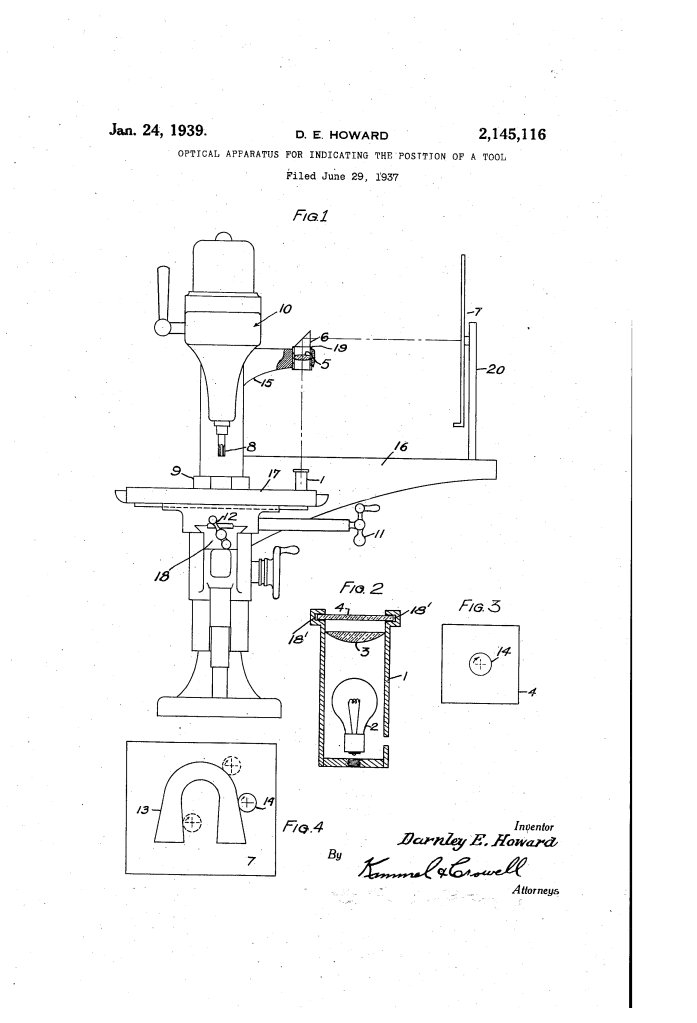
1. The Illuminable Simulation Slide (4)
A photographic slide (4) is created containing a precise circle (14) that matches the diameter of the cutting tool (8).
- Modern Term: Virtual Tool Overlay / Optical Template.
- This slide is mounted in a housing (1) on the machine’s moving platform (17). As the work moves, the slide moves in perfect synchronization.
2. The Optical Reflecting and Projecting Assembly
The apparatus uses a lamp (2), a lens system (3/5), and a prism (6) to gather the light from the slide and project it onto a remote screen.
- Modern Term: Overhead Projection / Optical Path.
- The prism (6) “deflects” the vertical beam of light horizontally toward the operator’s viewing screen, allowing the machinist to stay in a comfortable, upright position.
3. The Magnified Blueprint Screen (7)
A screen (7) is positioned in front of the operator, featuring a drawing (13) of the final part outline, typically at a scale of 5:1.
- Modern Term: Augmented Reality (AR) Workspace.
- Because the projected tool image is magnified by the same ratio as the drawing, the operator simply moves the machine controls to keep the “light-circle” touching the edges of the drawing.
4. The Motion Amplification Ratio
The accuracy of the system is governed by the distance between the lens and the screen.
- Modern Term: Scaling Factor / Geometric Gain.
- The formula for magnification M is defined by the ratio of the distance from the lens to the screen (d_i) to the distance from the lens to the slide (d_o):M = \frac{d_i}{d_o}An error of 0.005 inches at the tool is projected as a 0.025-inch gap on a 5x magnified screen, making it immediately visible to the naked eye.
Comparison Table
| Feature | Standard Machining (1930s) | Howard’s Optical Method |
| Layout Method | Scribed directly onto the steel. | Large-scale ink drawing on paper. |
| Visual Aid | Eye-strain or microscopy. | Naked-eye observation of a projected image. |
| Tool Accuracy | Manual measurement & trial-and-error. | Real-time “virtual” tool tracking. |
| Duplicate Parts | Layout must be repeated for every part. | Same drawing used indefinitely. |
Significance Section
- Precursor to CNC Visualizers: The logic of seeing a “virtual tool” move along a “digital path” is exactly how modern CNC (Computer Numerical Control) software displays machining paths today.
- Ergonomic Safety: By removing the need for the operator to hover over the spinning tool and oil spray, the device significantly reduced workplace eye strain and injury risk.
- Precision without Specialized Tools: It turned a standard vertical miller into a “Jig Borer,” allowing general shops to perform high-precision work without investing in single-purpose machines.
- Remote Control Potential: Howard explicitly noted that if the projection was large enough, the operator could sit back and operate the machine via remote control, a visionary concept for 1937.
