
Multiple Stage Rocket, Abner Samms, Patent No. 3,199,455
The patent by Abner Samms describes an aerospace engineering layout designated as U.S. Patent No. 3,199,455. This invention is a structural rearrangement of launch vehicles that replaces traditional vertically stacked, serial stages with a nested, concentric cluster array. By wrapping pairs of semicircular, expendable liquid propellant tanks collard around a core rocket body, the vehicle distributes cross-fed fuel and oxidizer to a single centralized engine. When a peripheral tank pair is exhausted, an onboard controller triggers pyrotechnic separations to strip the outer collar away. This concentric configuration shortens the overall vehicle profile, removes heavy internal load-bearing interstage structures, and uses spring-driven mechanical swing-arms to isolate exposed propellant fluid manifolds automatically after each separation event.
The “Why” (The Aerospace Engineering Pain Point)
During the early years of the space race, multi-stage launch vehicles followed a standard inline stacking architecture. Rockets were placed on top of one another in a long, serial vertical column, which created severe mechanical vulnerabilities.
- Structural Weakness: High-aspect-ratio, overly elongated airframes were highly susceptible to structural bending moments, aerodynamic shear stresses, and extreme vibration profiles during maximum aerodynamic pressure (Max Q).
- Dead Weight Penalty: To prevent the vehicle from buckling under load, engineers had to reinforce the upper stages with heavy, load-bearing internal structural trusses and interstage adapter rings. Each stage required its own dedicated rocket engine and complex start-up fluid loops. This design added massive dead weight to the vehicle, since spent inline frames had to be carried along until the next forward linear separation joint fired.
- Plumbing Complexity: Attempts to bypass this by utilizing secondary external tanks suffered from messy fluid line breakaways, which exposed the main internal fuel pumps to catastrophic drop-offs in fluid pressure or open-air flame blowbacks.
Inventor Section: Engineering Philosophy
Abner Samms was a highly innovative African American inventor whose design philosophy focused on structural simplification, extreme weight minimization, and spatial efficiency. Working during the heights of the Cold War aerospace boom, Samms targeted the unnecessary mass penalties of traditional staging configurations. He recognized that the most efficient way to scale a launch vehicle was to compress its geometry radially rather than expanding it linearly.
Samms viewed the outer skin of the rocket not merely as an aerodynamic shield, but as an active, interlocking component of the propulsion matrix. His designs emphasized automated mechanical safeguards—relying on robust, spring-driven kinematics over delicate electronics to execute reliable fluid isolation under the extreme g-forces and thermal stresses of supersonic flight.
Key Systems Section
Concentric Modular Tank Collar Assembly
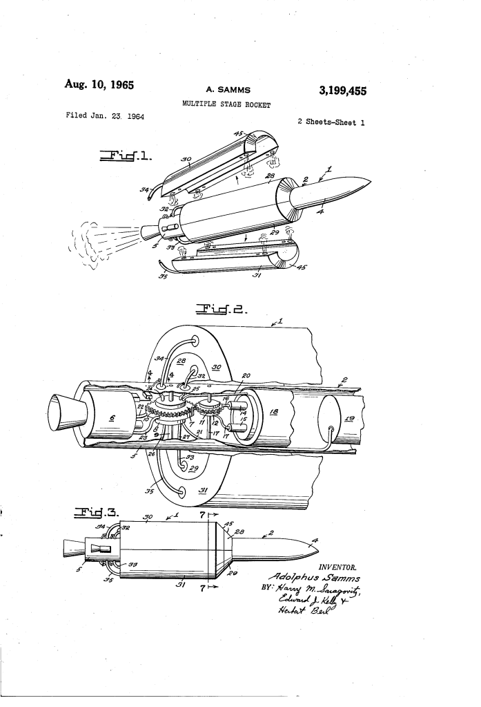
- Concentric Staging Topology: The rocket airframe shifts away from linear vertical stacking to a nested radial layout. The central core vehicle (2) functions as the core third stage, housing internal fuel (18) and oxidizer (19) tanks coupled directly to a single main combustion chamber (6).
- Segmented Semicircular Collars: Encircling this core body are nested pairs of matching semicircular tank halves. The second stage consists of a fuel tank (28) and an oxidizer tank (29) clamped directly onto the skin of the core tubular frame. The first stage consists of a larger-diameter fuel tank (30) and oxidizer tank (31) that wrap around the second-stage collar. To preserve aerodynamic efficiency, the forward rims of all external tank segments are shaped with a distinct bevel (45) to slice through incoming supersonic air streams.
Synchronized Turbo-Pump Cross-Feed Architecture
- Single-Drive Common Shaft: To eliminate the dead-weight penalty of flying separate engines for every stage, a single centralized rocket motor handles propulsion throughout the entire flight profile. A turbine (12) driven by solid-propellant starters (14, 15) operates a dual-set system of high-capacity fuel pumps (7) and oxidizer pumps (8) mounted symmetrically on a common drive shaft (9).
- Radial Multi-Inlet Manifolds: Main input lines loop from the pump inlets out to the exterior perimeter of the rocket body, splitting into dedicated stage inlet ports (24, 25, 26, 27). High-pressure flexible jumpers (32, 33, 34, 35) link these ports directly to the active outer collar tanks. This layout enables the central turbo-pumps to draw propellants from the outermost collar first, keeping the core interior tanks completely topped off and ready for the final leg of flight.
Pyrotechnic Jettison and Structural Release Array
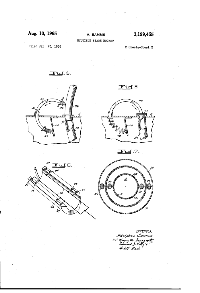
- Explosive Structural Tie-Bolts: The outer semicircular tank halves are locked into a rigid, structural ring around the vehicle by high-tensile explosive tie-bolts (36). These bolts hold the tanks secure against intense aerodynamic buffet loads during early ascent.
- Positive Outward Kick-Charges: Embedded into the inner lining of each semicircular shell are specialized explosive separation charges (37). When the flight programmer detects that a stage’s fuel supply is completely depleted, it fires the explosive tie-bolts while simultaneously igniting the backing kick-charges. This dual action splits the tank halves apart and drives them laterally away from the rocket, clearing the path for the vehicle without risking a structural collision with the inner hull.
Automatic Mechanical Fluid Isolation Valves
- Kinematic Spring-Driven Tracking: The exterior hull ports feature an elegant, fail-safe mechanical sealing valve to prevent flame backflow or pressure loss upon tank release. An arcuate (curved) tracking arm (40) is seated inside a custom guide channel (41) behind the outer skin.
- Positive Sealing Flip-Plugs: The curved arm terminates in a resilient, high-density rubber sealing plug (42) and is continuously tensioned by an internal return spring (43) anchored to a structural support bracket (44).
- Snap-Action Isolation Closure: While a tank is connected, its rigid line nipple (39) pushes past the plug, holding the spring-loaded arm back. The moment the tank is jettisoned and the nipple slips free, the tensioned arm snaps clockwise, driving the rubber plug into the open inlet port to form a reliable seal against vacuum leaks and thermal back-exposure.
Comparison Table
| Technical Metric / Feature | Standard Methods of the Time (Inline Stacking Architecture) | The New Innovation (Samms Concentric Cluster System) |
| Stage Configuration Geometry | Slipped inline vertically, creating a highly elongated, thin rocket profile. | Symmetrically nested radially, creating a shorter, wide-diameter vehicle. |
| Engine Distribution Matrix | Requires distinct rocket engine arrays and ignition loops for every stage. | Uses a single centralized engine and pump system for all stages. |
| Dead Weight Structural Load | Requires heavy structural interstage adapters and reinforced load walls. | Eliminated. Semicircular tank shells function as their own temporary load walls. |
| Separation Clearance Axis | Linear rearward axial drift; runs a high risk of interstage collision or scraping. | Lateral outward radial push using synchronized backing kick-charges. |
| Fluid Manifold Re-Sealing | Complex, multi-moving-part telemetry valves prone to pressure lockups. | Snap-action, spring-driven arcuate mechanical swing-arms. |
Significance Section
- Foundation for Heavy-Lift Parallel Booster Clusters: The architecture of feeding a central core sustainer engine from expendable, form-fitting side tanks laid the direct baseline for modern heavy-lift booster profiles, such as the Space Shuttle’s external tank and liquid rocket strap-on boosters.
- Evolution of Cross-Feed Fuel Management: Samms’ cross-feed methodology, which draws fuel from external strap-on elements into central turbo-pumps to keep core tanks full at liftoff, anticipated advanced modern rocket fluid management paths used to maximize payload capacity.
- Pioneered Compact Weapon Profile Design: By compressing the structural envelope of a multi-stage missile, this patent enabled the development of shorter, high-velocity tactical weapons that could be stored, transported, and launched from compact mobile platforms or tight subterranean silos.
Next Step
To evaluate the vehicle’s structural performance, the next step is to calculate the Aerodynamic Center of Pressure Shift during stage separation. By modeling the aerodynamic drag equation:
F_D = 1/2 rho v^2 C_D A
against the cross-sectional area (A) and drag coefficient (C_D) before and after the first-stage semicircular collars (30, 31) are jettisoned, engineers can determine how the lateral displacement of mass alters the vehicle’s stability margin (C_P – C_G). This analysis ensures that the control system can easily adjust for the rapid change in aerodynamic forces without causing the rocket to tumble as the outermost tanks break away.
