
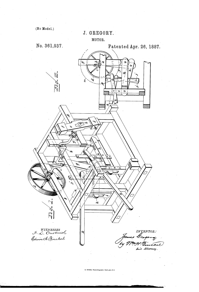
The patent by James Gregory of Bogansville, South Carolina, describes a Mechanical Motor (Patent No. 361,937, 1887). The invention is a human-powered machine designed to drive various kinds of machinery. It utilizes a sophisticated system of levers and a balanced beam to convert manual, vertical motion into continuous rotary power, specifically aimed at rural districts where steam or horse-power might be unavailable.
Inventor Background: James Gregory
James Gregory was an African-American inventor from Union Township, South Carolina. Patented in 1887, his mechanical motor highlights the era’s focus on amplifying human physical labor through mechanical advantage. In post-Reconstruction South Carolina, small-scale farmers and tradesmen often lacked access to expensive coal-fired steam engines. Gregory’s invention provided a “middle-tech” solution—using iron and wood to build a motor that a single person could operate to power heavy tasks like grinding, sawing, or pumping water.
Invention and Mechanism (Simplified)
The motor works by coordinating hand-levers with a crank-shaft, using a weighted beam to maintain momentum.
1. The Lever Assembly (Third Order Levers)
- Hand-Levers (k) and Links (j): The operator works the motor by moving two hand-levers (k) up and down. These are “levers of the third order,” connected by vertical links (j) to a second set of levers (h).
- Mechanical Advantage: Gregory designed these links to be adjustable. By moving the pivot points, the “throw” of the motion can be varied to suit the machinery being driven—longer leverage for heavy loads, shorter for light tasks.
2. The Crank-Shaft and Pitman-Rods
- Pitman-Rods (g): These rods connect the levers ($h$) to the cranks (c) of a horizontal shaft.
- Rotary Conversion: As the operator pumps the hand-levers, the vertical motion is transferred through the pitman-rods to the cranks, forcing the crank-shaft to rotate.
3. The Balanced Beam (e) (Key Innovation)
- Momentum Control: Instead of a standard solid fly-wheel, Gregory used a balanced beam (e) fixed to the shaft.
- Adjustable Counter-Weights (f): Heavy weights are slid along the beam to vary its inertia.
- Function: Once the operator sets the beam in motion, its momentum helps overcome the “dead centers” of the crank movement. The beam’s weight assists in the vibration of the levers, effectively acting as the “controlling element” that keeps the motor spinning smoothly with less physical effort from the operator.
4. Power Transmission
- Pulley (d): At one end of the shaft, a band-pulley (d) transmits the generated power to the desired machinery via a belt. Gregory also noted that gear-wheels or a simple crank could be used depending on the task.
Concepts Influenced by This Invention
Gregory’s mechanical motor influenced the design of manual power-augmentation tools and demonstrated advanced principles of inertia-based motion.
- Adjustable Inertia Systems: The use of sliding counter-weights to tune a machine’s momentum is a fundamental engineering principle. Modern variations of this are found in adjustable flywheels used in industrial balancing and high-performance exercise equipment.
- Compound Lever Linkages: By nesting one lever system inside another, Gregory demonstrated how to increase mechanical advantage in a compact space, a precursor to the complex linkages used in manual printing presses and agricultural equipment.
- Decentralized Mechanical Power: This invention was an early example of “appropriate technology”—designed specifically for the constraints of its users (rural, limited resources). This philosophy continues today in the development of human-powered water pumps and grain mills for developing regions.
- Conversion of Reciprocating Motion: The motor refined the logic of the foot-treadle (like those on old sewing machines) but adapted it for the greater strength of the arms and the weight of a balanced beam, providing a more powerful output for heavy-duty industrial work.
