
Method of Making Radome with an Integral Antenna (1969)
U.S. Patent No. 3,451,127, granted on June 24, 1969, to Darnley M. Howard and Irving Mathis (assigned to the United States of America as represented by the Secretary of the Navy), addresses a critical signal distortion and sensitivity problem in high-speed military aircraft and naval ordnance: the physical separation between an antenna and its protective housing (radome).
In conventional installations, a separate antenna structure was mounted inside an external radome shell. Under intense flight vibration, aerodynamic buffet, and mechanical shocks, any relative motion between the antenna and the radome generated severe electrical interference known as microphonics, leading to degraded signal reception and loss of sensitivity. Howard and Mathis, working out of College Park, Maryland, solved this by creating a method to integrate the conductive antenna elements directly onto the inner wall of the radome shell as a single bonded unit.
The Core Innovation: Direct-Substrate Metallization and Pore-Burnishing
Prior attempts to mount antennas inside radomes relied on mechanical standoffs, brackets, or separate reflector frames. These assemblies not only added weight and complexity, but vibrations inevitably caused microscopic shifts between the RF radiator and the dielectric wall.
Howard and Mathis eliminated all relative motion by metallizing the antenna directly onto the contoured inner surface of a silicone-glass laminate radome. Their key breakthrough was a multi-stage deposition process that pairs mechanical abrasion with chemical seeding and burnishing, forcing conductive material deep into the microscopic pores of the dielectric substrate before electroplating the final conductive traces.
Why the Integral Construction?
Elimination of Microphonics: Because the antenna metal forms an unbroken, intimate bond with the radome substrate, relative motion between the two is completely impossible, eliminating microphonic noise.
Preserved Sensitivity: Removing physical gaps, secondary supports, and vibration-induced resonance ensures consistent RF transmission and prevents degradation of receiver sensitivity.
Vibration and Thermal Resistance: The combination of a heat-stable silicone-glass matrix and burnished metallic bonding withstands extreme operational temperatures and high-G flight environments.
Key Technical Components
The assembly integrates composite dielectric materials with plated metallic conductors:
| Component | Function |
| Cylindrical Radome Shell (10) | Formed from a heat-stable, water-repellent silicone-glass plastic laminate; serves as the aerodynamic housing and electrical substrate. |
| Roughened Substrate Interface | Prepared using a mild abrasive to create microscopic surface pores and tooth that ensure mechanical interlock for the metal. |
| Preliminary Conductive Layer | A thin film of conductive silver paint or vacuum-deposited silver; seeds the dielectric surface in the precise antenna geometry. |
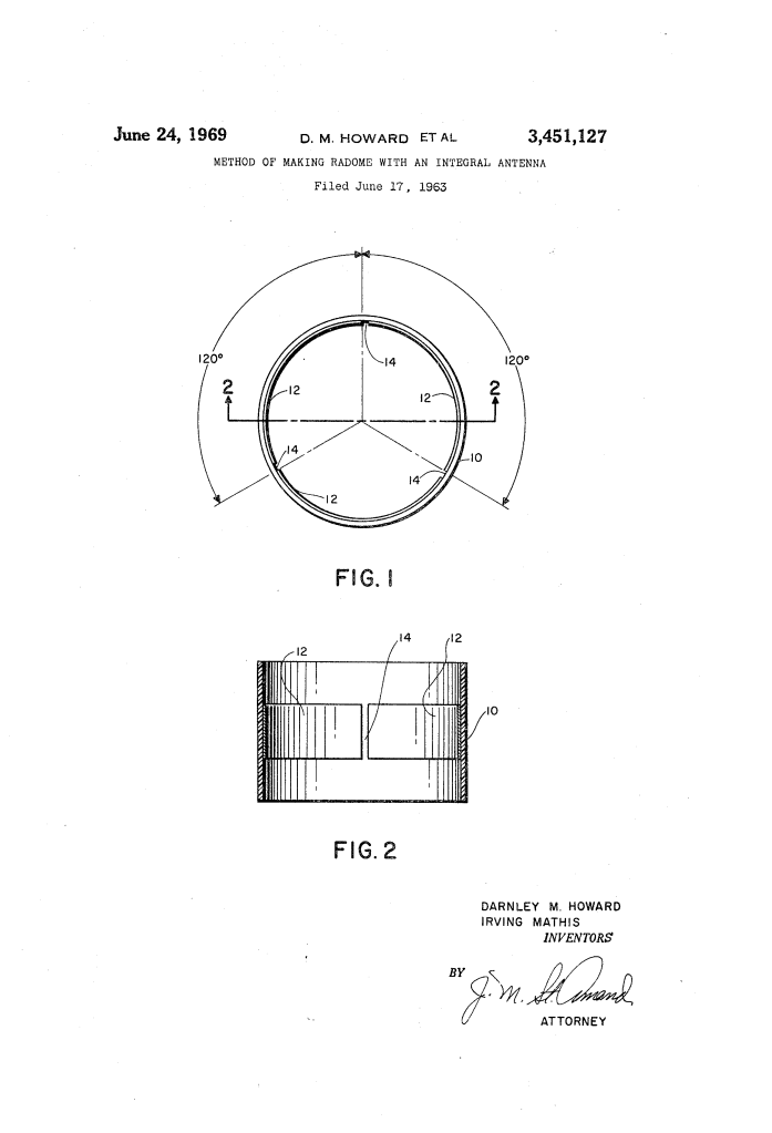
| Segmented Antenna (12) | Final electroplated conductive paths (shown in three segments separated by gaps 14); carries the RF signal without mechanical movement. |
How the Manufacturing Process Works
The fabrication process follows a precise mechanical and electrochemical sequence:
| Step | Action | Operational Purpose |
| 1. Substrate Formation | Mold a hollow, cylindrical radome shell from a heat-stable, water-repellent silicone-glass laminate. | Establishes the structural radome body with compatible dielectric and mechanical properties. |
| 2. Surface Preparation | Roughen the interior surface of the radome using a mild abrasive, followed by thorough chemical cleaning. | Creates open microscopic pores to facilitate mechanical adhesion of conductive coatings. |
| 3. Seed Coating | Apply a preliminary thin coating of silver conductive paint (or vacuum-deposited silver) in the antenna pattern. | Establishes the initial geometry and electrical continuity across the desired radiating layout. |
| 4. Pore Burnishing | Mechanically burnish the preliminary conductive coating into the microscopic surface pores of the laminate. | Ensures unbroken electrical continuity and prevents delamination under stress. |
| 5. Electroplating Build-Up | Electroplate silver or another suitable conductive metal directly onto the burnished seed layer. | Builds the antenna traces to their full required electrical skin depth and operational thickness. |
| 6. Final Burnishing | Burnish the electroplated antenna metal across its finished surface. | Smooths the conductive surface finish and consolidates the metal structure. |
Historical and Military Impact
Patented under assignment to the U.S. Navy during the height of the Cold War, Howard and Mathis’s invention provided crucial advancements for radar and guided missile guidance systems:
- Ordnance and Missile Guidance: Guided missiles and compact naval radar heads operate under violent launch accelerations. Eliminating internal brackets and mechanical antenna mounts allowed assemblies to endure high shock loads without signal dropouts.
- Weight and Space Reduction: Plating conductive traces directly onto the inner surface of the aerodynamic radome shell removed the hardware footprint and mass of standalone antenna frameworks.
- Foundation for Modern Conformal Antennas: This early integration of metallic radiating elements onto dielectric composite radomes served as a direct precursor to modern conformal antennas, printed array radomes, and stealth aerospace structures.
About the Inventors: Darnley M. Howard and Irving Mathis
Darnley M. Howard was a distinguished African American mechanical engineer and inventor whose career spanned significant contributions to defense, aerospace, and biomedical engineering. A graduate of Howard University, he worked extensively in government research laboratories—including the Naval Ordnance Laboratory in White Oak, Maryland—and in private industry, securing patents across mechanical assemblies, ordnance systems, and specialized manufacturing methods. Together with Irving Mathis, his work in College Park, Maryland, bridged advanced materials engineering with precision microwave instrumentation.
Summary of Claims
The patent explicitly claims:
- A method of fabricating an integral antenna-radome unit that eliminates microphonics caused by relative motion, comprising the steps of forming a hollow radome from silicone-glass laminate, abrasive roughening of the interior, applying a preliminary thin conductive coat, burnishing the coat into the substrate pores, applying antenna metal to the desired thickness, and burnishing the final metal.
- The use of silver conductive paint as the preliminary conductive layer.
- Applying the preliminary conductive coating via vacuum deposition.
- Building up the final antenna metal thickness by electroplating directly onto the burnished preliminary coating.
- The specific use of silver as the electroplated antenna metal.
