

Metal-Bending Machine (Thomas W. Stewart, No. 375,512)
The patent by Thomas W. Stewart of Kalamazoo, Michigan, describes a Metal-Bending Machine (Patent No. 375,512, 1887). This invention is a power-operated industrial tool designed to bend metal bars into specific angles or curves with high precision and minimal manual effort. Stewart’s primary innovation was the integration of a clutch mechanism and an oscillating disk that allowed the machine to perform a complete bending cycle and then automatically disengage, preventing over-bending and increasing the efficiency of the manufacturing process.
Inventor Background: Thomas W. Stewart
Thomas W. Stewart was a prolific African American inventor best known for his 1893 patent of the modern mop. However, his 1887 metal-bending machine showcases his deep expertise in heavy industrial engineering. During the late 19th century, as the American manufacturing sector exploded, tools that could be run by “power mechanism” rather than human muscle were in high demand. Stewart’s design demonstrates a masterful grasp of kinematics—the geometry of motion—and provided a robust solution for blacksmiths and factory workers.
Key Mechanical Components & Functions
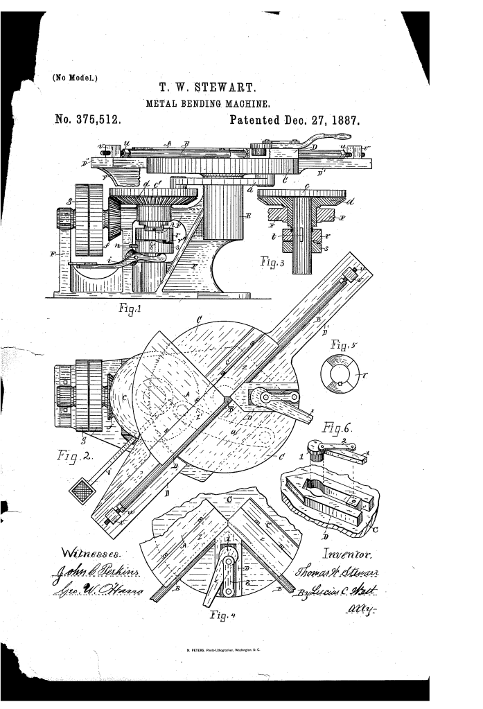
The machine utilizes a rotating crank to drive an oscillating bending head, controlled by a foot-treadle.
1. The Fixed Shelf and Oscillating Disk (D, C)
- The Base: The metal bar (B) is supported on one side by a fixed shelf (D) and on the other by a laterally projecting arm (D’).
- Headed Screws (U): These screws pass through lugs (V) to hold the ends of the bar firmly in place, ensuring it does not slip during the bending process.
2. The Forming Blocks and Dies (A, Z)
- Block A: A rigid block attached to the shelf acts as the “anchor” for the bend.
- The Raised Portion (C’): The oscillating disk (C) has a corresponding raised section that moves against the bar.
- Interchangeable Dies (Z): Stewart designed the machine to use detachable dies (Z).
- Function: By swapping dies, the machine could create square bends, concave curves, or other shapes depending on the geometry of the die face.
3. The Sliding Clamp Block (D”) (Key Innovation)
To prevent the metal from buckling, it must be clamped tightly against the forming block.
- Eccentric Lever (X): A sliding block (D”) is operated by an eccentric lever (X).
- Mechanism: When the lever is swung, a strap (2) and lug (1) cause the block to slide forward, wedging the bar (B) into the groove of the die (Z). This ensures the metal is fully supported at the exact point of the bend.
4. The Automatic Clutch Mechanism (r, s, d)
This is the “brain” of the power-operated system.
- The Crank-Disk (O’): Power is applied via a belt to a hand-wheel (g) and gear (f), which turns the crank-disk (O’).
- The Collars (r, s): Two collars sit on the shaft. The upper collar (r) revolves with the shaft (held by a spline t), while the lower collar (s) is loose and prevented from turning by a projection (n).
- Treadle Operation (z): When the operator steps on the treadle (z), it raises both collars.
- Action: The upper collar engages a tenon on the bevel-gear (d), starting the bending motion.
- Automatic Stop: The contiguous edges of the collars have raised and depressed portions. Once the bend is complete, these portions “register” (align) with each other, causing the collars to drop and automatically disengage the gear. This stops the machine at the perfect moment.
Improvements Over Manual Bending
| Feature | Manual Blacksmithing | Stewart’s Bending Machine |
| Power Source | Human muscle and hammer. | Mechanical power (belt/gears). |
| Consistency | Highly dependent on the smith’s skill. | Automatic clutch ensures every bend is identical. |
| Versatility | Limited by fixed anvils. | Interchangeable dies (Z) allow for various shapes. |
| Safety/Effort | Labor-intensive and slow. | Foot-treadle operation allows for “hands-free” power control. |
Significance to Mechanical Engineering
Thomas W. Stewart’s metal-bending machine influenced the development of automated fabrication and machine safety logic.
- The Cycle Stop Principle: The idea of a machine that automatically stops itself after a specific mechanical cycle is a fundamental concept in modern CNC machining and stamping presses.
- Eccentric Clamping: Stewart’s use of an eccentric lever for rapid, high-pressure clamping is a standard engineering technique still used in industrial jigs and fixtures today.
- Modular Tooling: By designing the machine to accept different dies, Stewart anticipated the flexible manufacturing systems that allow a single machine to produce a wide variety of parts.
- Kinematic Linkage: The use of a connecting rod (a) to translate the rotation of a crank into the oscillation of a disk is a classic application of the four-bar linkage, essential for converting motor power into specific task-oriented movements.
