

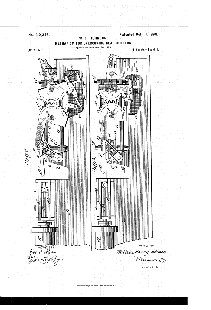
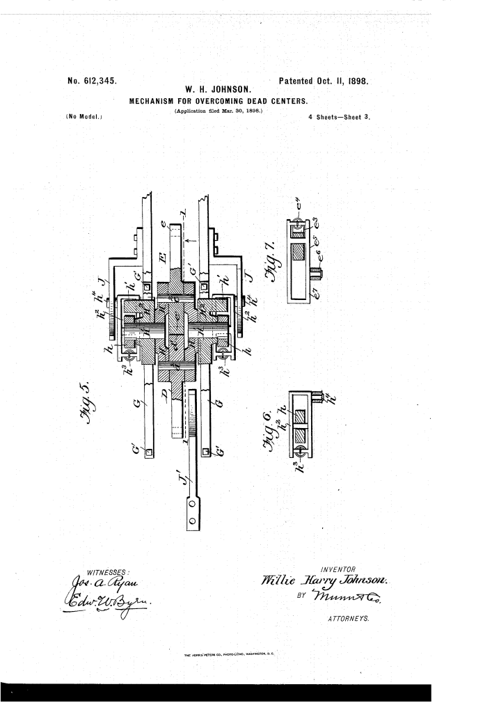
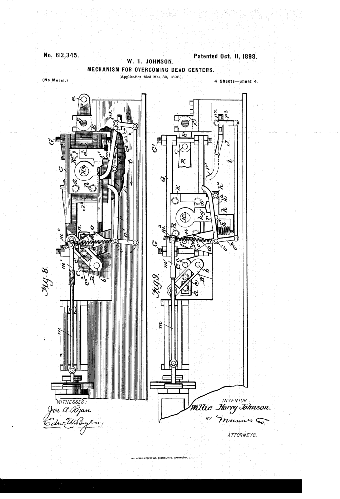
Mechanism for Overcoming Dead-Centers (1898)
U.S. Patent No. 612,345, granted on October 11, 1898, to Willie H. Johnson, describes an ingenious mechanical linkage designed to eliminate the notorious “dead-center” stall inherent in reciprocating steam engines. Willie Harry Johnson, an inventor based in Navasota, Texas, focused his efforts on overcoming one of the fundamental engineering hurdles of nineteenth-century machinery.
In a conventional engine, when the piston rod, connecting rod, and crank pin align in a straight line at the extreme ends of a stroke, the engine exerts zero rotational torque—a vulnerable state known as dead center. Johnson’s patent refined his earlier 1896 design to produce a lighter, lower-friction mechanism that not only forces the crank past these stalling positions but also times the admission of steam to deliver useful work precisely at the dead center.
The Innovation: The Alternating Fulcrum System
Johnson’s core breakthrough is an intermediate linkage between the engine’s connecting rod and the driven crank that dynamically alternates between operating as two independent rocking levers and operating as a single, unified rigid lever.
By shifting the effective center of oscillation at precise moments during the stroke, the mechanism continuously maintains angular leverage over the crank pin:
Dual-Center Mode: The two rocking heads rotate independently on separate axes via intermeshed gear segments, providing an upward thrust that sweeps the crank off the dead center.
Single-Center Mode: Automatic locking yokes lock the two heads together, converting them into one rigid structure rocking about a central trunnion to provide the reverse downward thrust needed to carry the crank through the opposite dead center.
Key Mechanical Components
The assembly relies on coordinated gear segments, locking yokes, and sliding supports:
| Component | Function |
| Rocking Heads (D and E) | Opposed heads fitted with intermeshing toothed segment-gears (d’ and e’) that transmit and reverse motion between the linkage and crank F. |
| Abutting Stop-Faces (x and y) | Contact faces on the lower sides of the segment gears that arrest gear motion to align centers precisely during sliding travel. |
| Head-Locking Yoke (e5) | A spring-loaded latch (e4) that snaps over arm d3 to lock heads D and E into a single, rigid lever unit. |
| Side Plates and Trunnions (H, H’) | Journal plates supporting the rocking heads, mounted on central trunnions that slide along guides G within bearing-plates H2. |
| Trunnion-Locking Yoke (h2) | A spring-actuated latch (h3) that locks arms h and h’ to selectively prevent or permit rotation around the central trunnions. |
| Stationary Cam Bars (J and J’) | Inclined trip ramps that deflect pins h4 and e6 to unlock the respective yokes at specific points along the stroke. |
| Correlated Valve-Gear (n, o, r, r’) | A slide-valve linkage operated by tappet arms that fire steam into the cylinder at the exact instant dead center is reached. |
How the Mechanism Operates
The mechanism transitions seamlessly between independent and locked states across the cycle:
- Initial Stroke (Two Centers Active): As the piston pushes arm B and arm C upward, rocking head D rotates about axis d2. Its segment gear d’ drives gear e’ on head E, lifting crank F cleanly off dead center.
- Carriage Shift: As the piston nears the end of its stroke, the entire assembly of heads D, E, and journal plates H slides horizontally along the outer guides.
- Locking the Heads: As pin e6 clears inclined bar J’, spring e4 snaps yoke e5 over arm d3. Heads D and E are now locked into a single rigid beam.
- Releasing the Trunnions: At the extreme right of the stroke, pin h4 strikes inclined bar J, tripping yoke h2 and freeing central trunnions H’ to pivot.
- Reverse Thrust (Single Center Active): On the return stroke, arms B and C rise again. Because heads D and E are locked as one lever around central trunnion H’, the crank end of E is forced downward, driving crank F smoothly past the second dead center.
- Resetting: Passing back to the left, trip bars re-engage and release the appropriate yokes, resetting the gears for independent action on the next stroke.
Correlated Valve Action
To maximize efficiency, Johnson recognized that overcoming the physical dead center allowed the engine to perform actual work where standard engines were powerless. He correlated the engine’s slide valve directly to the locking yokes:
When yoke e5 snaps shut to couple the heads, it simultaneously strikes and raises tappet arm r’, shifting the valve rod m to admit fresh steam at that exact fraction of a second.
When yoke h2 trips at the opposite limit, it raises tappet arm r, reversing the valve gear and admitting steam for the counter-stroke.
A toggle spring (w) snaps across the fulcrum of lever n, holding the slide valve securely in position between transitions.
About the Inventor: Willie H. Johnson
Willie Harry Johnson was an African American inventor working in Navasota, Grimes County, Texas, during the late nineteenth century.
Patents and Ingenuity: Operating during a prolific era of post-Reconstruction mechanical innovation, Johnson secured multiple U.S. patents, including Patent No. 554,223 (granted in 1896) and this refined mechanism in 1898 (Patent No. 612,345).
Engineering Legacy: Mechanical dead centers were among the most widely debated engineering challenges of the steam era, responsible for stalled factory engines, marine delays, and complex locomotive starting issues. Johnson’s design demonstrated sophisticated kinematics, combining compound leverage, automatic spring-tripped clutches, and integrated valve timing in a unified mechanical solution.
Summary of Claims
The patent explicitly claims:
The combination of two rocking heads with intermeshing segment gears mounted on reciprocating journal plates having both individual axes and a common intermediate fulcrum.
Locking devices (yokes e5 and h2 with spring tension and stationary release bars) configured to alternate the mechanism between rocking about individual axes and rocking about a shared common axis.
Abutting stop-faces (x, y and x’, y’) arranged on the gears and arms to ensure precise alignment of centers during horizontal sliding thrusts.
A coordinated valve-gear system comprising segment levers and tappet arms triggered directly by the locking yokes to inject steam into the cylinder at the exact dead-center positions.
