
Mechanism for Overcoming Dead-Centers (1896)
U.S. Patent No. 554,223, granted on February 4, 1896, to Willie Harry Johnson, describes a mechanical system designed to automatically force a engine’s crank-arm past its “dead-center” positions. Willie Harry Johnson, an inventor based in Navasota, Texas (Grimes County), created this mechanism to solve one of the most fundamental inefficiencies in reciprocating steam engines and crank-driven machinery.
This specific invention solved a persistent problem in 19th-century mechanical engineering: the loss of leverage and stalling that occurs when a piston rod, connecting rod, and crank-pin line up in a straight line at the ends of a stroke, where linear force cannot generate rotational torque.
The Innovation: The “Two-Part Compound Crank-Rod”
In standard engines, a single rigid connecting rod links the piston to the crank. When the piston reaches the exact end of its forward or backward stroke, the rod pushes directly against the center of the shaft, stalling the engine unless momentum or a heavy flywheel carries it past.
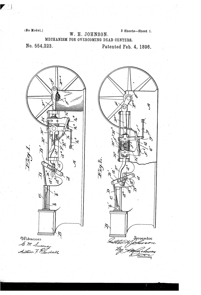
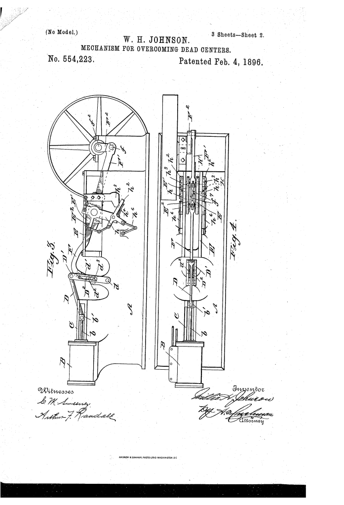
Johnson’s breakthrough was replacing the rigid rod with a two-part, cross-shaped compound crank-rod (F, F) that automatically locks together to act as a single rigid bar during parts of the stroke, and automatically unlocks to flex and apply an upward or downward angular thrust right at the dead-center points.
How the Compound Rod Works
- Locked State (Forward Pass): The two cross-shaped members (F and F) are held rigid by a spring-loaded locking strap (G). As the piston moves, the entire assembly pivots as a single unit on a sliding block (E), driving the crank-pin (f) downward past the first dead-center line.
- Unlocked State (Return Pass): As the crank reaches the opposite end, a fixed linkage (g) automatically pulls the locking strap off. The two cross members (F, F) are now free to pivot independently on their individual central pins (H).
- The Toggle Action: When unlocked, the inner ends of F and F are connected by toggle links (f). As the upper arm is lifted by a leverage assembly, the inner toggle forces the main crank-arm F to tilt in the opposite direction, applying a direct vertical force that pops the crank-pin past the opposite dead-center.
Key Mechanical Components
The apparatus uses an intricate system of sliding pivots, levers, and spring-loaded latches to manage the dual-action stroke:
| Component | Function |
| Compound Crank-Rod (F, F) | Two cross-shaped, toggle-linked members that alternate between acting as a rigid beam and a pivoting leverage system. |
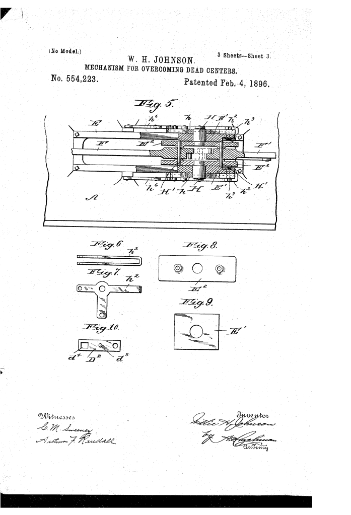
| Sliding Block & Guide (E, E1) | Provides a movable foundation for the main pivots (H), allowing the entire assembly to reciprocate horizontally with the engine stroke. |
| Locking Strap (G) & Spring (G1) | Secures foot g2 on member F to lock both halves together; spring G1 automatically re-engages the latch when aligned. |
| T-Arms ($h$) & Straps (h2) | Secondary locking mechanisms that hold the mounting plates (E2) stationary when individual member pivoting is required. |
| Leverage Arms (D1, D2) | A system of slotted, pivoted links driven by the main piston rod (b) to apply a crosswise thrust to the end of arm F. |
Operation: Overcoming the Dead-Center
The mechanism operates through a synchronized 4-step mechanical sequence:
- Approach First Dead-Center: The compound rod is locked rigid by strap G. The piston pushes the sliding block (E1) forward while the slotted lever arm (D2) lifts arm F.
- First Push-Through: Because the rod is locked, the upward lift on arm $F$ forces the opposite end holding the crank-pin (f) directly downward, rotating it past the zero-torque line.
- Automatic Unlocking: At the end of the stroke, stationary linkage g yanks strap G free. Simultaneously, straps h2 lock the base plates (E2) in place.
- Second Push-Through: On the return stroke, lever arm D2 pulls downward on arm F. Because F and F are now unlocked, they pivot around individual pins (H), causing the internal toggle links (f’) to push arm F upward, driving the crank-pin past the second dead-center.
About the Inventor: Willie Harry Johnson
Willie Harry Johnson was a 19th-century inventor operating out of Navasota, Texas.
- Context: Operating during the height of the American Industrial Era, Johnson focused on fundamental mechanical improvements to steam locomotion and stationary engine efficiency.
- Impact: Dead-centers were a primary cause of engine stalling, requiring complex multi-cylinder arrangements, massive flywheels, or manual levering to restart heavy machinery. Johnson’s invention offered an automated structural solution contained entirely within the linkage mechanism.
Summary of Claims
The patent explicitly claims:
- A crank-rod composed of two members that are locked together during a portion of the stroke and move independently during the remainder.
- Automatic locking and unlocking mechanisms (spring-pressed straps and unlatching links) triggered at predetermined points in the engine’s stroke.
- A pivoting, sliding block assembly (E, E1, E2) that allows the compound rod to undergo both horizontal reciprocation and angular thrust.
- Secondary mechanical leverage connections (D1, D2) between the main reciprocating piston and the compound rod to apply force at right angles to the line of reciprocation.
