
Mechanism for Distributing Tacks, Nails, &c. (1889)
U.S. Patent No. 415,726, granted on November 26, 1889, to Jan Ernst Matzeliger (recorded in the patent specification as Jan Earnst Matzeliger), details an ingenious feeder system designed to take a jumbled pile of loose tacks or nails, line them up straight, and deliver them one by one down a guided track at steady, timed intervals. Matzeliger, an iconic inventor based in Lynn, Massachusetts, revolutionized footwear manufacturing through mechanical automation.
This invention solved a critical operational bottleneck in automated shoe lasting and high-speed manufacturing: bulk fasteners frequently entangled, jammed, or fed upside-down, causing continuous mechanical stoppage. Matzeliger designed a self-clearing, gravity-assisted raceway system that sorts, checks, and continuously unjams itself using the motion of the fasteners themselves.
The Innovation: The Self-Clearing Agitated Raceway
Bulk fasteners such as tacks and nails naturally clump together. Previous feeding methods frequently jammed whenever an improperly oriented tack reached the narrow guide track. Matzeliger overcame this by designing an articulated two-piece chute coupled with a tilting hopper, using kinetic motion and an overhanging stop bridge to regulate the line.
The breakthrough lay in utilizing the bulk mass of fasteners as its own mechanical clearing tool:
- Orientation Filtering: Tacks fall into a channel slot where their stems suspend downward while their heads slide along the polished upper edges.
- Bridge Clearance: An overhanging bridge sets closely above the track, admitting only properly seated tacks and physically blocking sideways or inverted fasteners.
- Active Mass Clearing: As the hopper rocks downward, excess bulk tacks slide back across the entry, physically sweeping tangled fasteners away from the bridge mouth to give them a second chance to align correctly.
Mechanical Components
Matzeliger integrated several precisely engineered mechanical parts to ensure continuous movement without manual intervention:
| Component | Function |
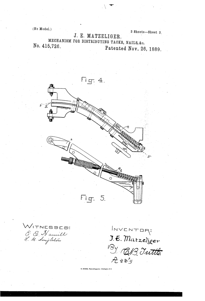
| Lower Fixed Chute (a) | A two-part polished steel raceway groove that conducts aligned tacks directly downward toward the separator and driving mechanism via vibration and gravity. |
| Upper Movable Chute (b) | Formed directly into the base of the hopper; connects to the fixed chute via an articulated joint that acts as the fulcrum during tilting. |
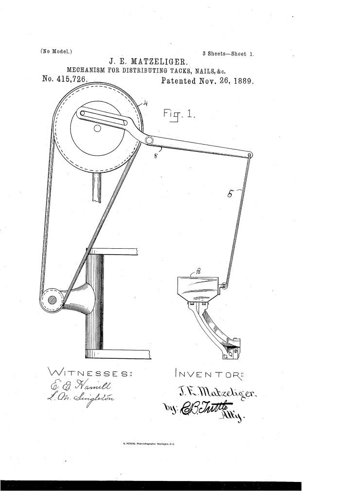
| Agitating Mechanism (4, 5) | A motorized crank-wheel (4) and pitman rod (5) that oscillate the hopper, repeatedly reversing the gravitational incline to shift the fasteners. |
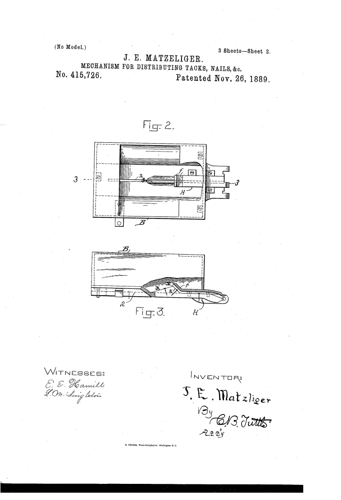
| Stop Bridge (f) | A rigid cover plate set over the raceway that sets a strict clearance threshold, blocking misaligned tacks from entering the feed track. |
| Inclined Cam Faces (y, z) | Beveled track edges that gradually widen upward and descend abruptly, guiding entering tack shanks into vertical alignment. |
How the Apparatus Functions
The mechanism operates in a continuous mechanical cycle driven by the oscillating pitman assembly:
| Step | Action | Mechanical Purpose |
| 1. Upward Stroke | The pitman rod lifts the rear end of hopper B, tilting loose tacks forward toward the chute mouth. | Gravitates the bulk load over the exposed channel a so stems drop into the slot. |
| 2. Bridge Passage | Properly suspended tacks slide under bridge f, supported by their heads. | Isolates aligned fasteners into single-file order; blocks raised or wedged tacks. |
| 3. Downward Tilt | The agitator lowers the rear of the hopper, reversing the slope of the exposed raceway. | Causes improperly aligned tacks outside the bridge to slide back into the hopper chamber. |
| 4. Self-Clearing Sweep | The moving bulk mass of loose tacks slides across the floor over the blocked raceway. | Acts as a natural mechanical drag to dislodge cramped tacks and clear the bridge mouth. |
| 5. Continuous Feed | Aligned tacks held past the curved rear track section glide downward without slipping back. | Maintains an unbroken supply of tacks to the discharge separator without jamming. |
Historical and Industrial Impact
While filed as an independent sub-system patent (Application Serial No. 287,908, filed October 12, 1888), this distributor formed a core operational organ of Matzeliger’s revolutionary automatic shoe-lasting machine ecosystem.
- Elimination of Hand Feeding: Manual shoe lasters held mouthfuls of tacks and placed them by hand. Matzeliger’s automated distributor proved that small, irregular fasteners could be fed mechanically at machine speed.
- Anti-Jamming Reliability: By designing the bulk articles to act as their own clearing brush, the machine achieved uninterrupted industrial operation without requiring manual clearing tools.
- Mass Production Enablement: Reliable tack delivery directly enabled the commercial success of automated lasting, cutting shoe manufacturing costs in half and making high-quality footwear affordable to the public.
About the Inventor: Jan Ernst Matzeliger
Jan Ernst Matzeliger (1852–1889) was an Afro-Surinamese inventor whose mechanical genius transformed the footwear industry and established Lynn, Massachusetts, as the shoe capital of the world.
- Patents: His landmark shoe lasting machine (U.S. Patent No. 280,086, issued in 1883) solved a mechanical puzzle long considered impossible by engineers. He followed it with multiple patents refining tack feeding, distribution, and automated nailing mechanisms (including Nos. 415,726 and 421,954).
- Impact: Before Matzeliger, lasting was a slow hand craft that capped factory output. His automated systems raised daily production from roughly 50 pairs a day per worker to upwards of 700 pairs.
- Legacy: Matzeliger passed away from tuberculosis in the summer of 1889 at age 36, just months before this specific patent was formally issued. His inventions laid the technical foundation for the Consolidated Lasting Machine Company and the United Shoe Machinery Corporation.
Summary of Claims
The patent explicitly claims:
- A feeding device for tacks and small articles comprising a chute with a continuous slot for fastener stems and an overhanging stop bridge crossing the slot below its upper end.
- An articulated chute combining a fixed lower section and an agitated movable upper section connected by a pivoting joint.
- A hopper formed with a slotted bottom continuous with the raceway, mounted to tilt on a fulcrum to agitate bulk articles.
- Dual inclined faces (y, z) flanking the chute raceway to direct and seat descending fastener heads.
- The combination of an agitated hopper, an overhung stop bridge, and a slotted chute arranged to let loose shifting articles clear stuck fasteners from the raceway mouth.
