
Cooling Means for Gas Engines, Frederick M. Jones (1949)
Patented in July 1949, this invention by Frederick M. Jones (U.S. Patent No. 2,475,843) is a strategic mechanical refinement of his “inside-out” starter generator. While the previous patent focused on the electrical architecture of the motor, this patent focuses specifically on thermal management—how to use that spinning motor to keep an air-cooled gas engine from melting down under heavy loads.
In the 1940s, portable gas engines used in refrigeration were often crammed into tight, unventilated compartments on trucks. Jones realized that he could use the physical mass of the starter generator not just to create electricity, but to act as a high-volume centrifugal air pump.
The “Why”
Air-cooled engines rely on a constant stream of air passing over metal fins to dissipate heat.
- The Problem: Separate fans and belt-driven blowers added bulk, required maintenance, and often didn’t provide enough “head pressure” to force air into every nook of a multi-cylinder engine.
- The Solution: Jones integrated curved blower vanes (46) directly onto the outer shell of the starter generator. By doing this, the cooling system became part of the engine’s primary drive shaft, ensuring that as long as the engine was running, it was cooling itself.
Inventor Section: Engineering Philosophy
Frederick M. Jones’s philosophy here was Integrated Aerodynamics. He understood that heat is the enemy of both gas engines and electrical insulation. By designing a specialized shroud (49), he forced the air to do double duty: first, it cools the electrical components of the generator to preserve its insulation, and then it is channeled over the engine’s radiator fins (56). This “serial cooling” ensures that the most temperature-sensitive parts get the coolest air first.
Key Systems Section
1. The Perimeter Blower Vanes
Instead of a separate fan blade, Jones used the wide diameter of the “inside-out” armature to his advantage.
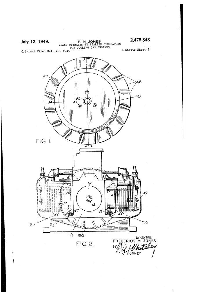
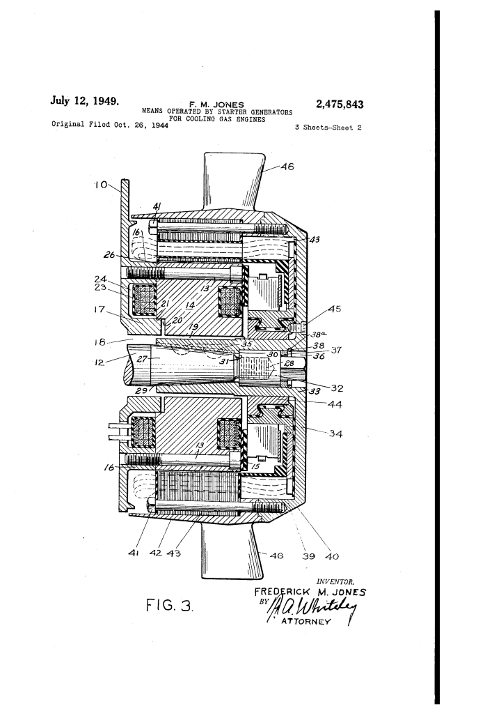
- The Vanes (46): A series of arcuately curved metal blades are bolted to the Blower Ring (42) on the outer periphery of the armature.
- The Physics: Because these blades sit at the outermost edge of the rotating assembly, they move at high speeds, generating a massive volume of air movement with very little extra power consumption.
2. The Multi-Cylinder Shroud
To make the air effective, it had to be “tamed” and directed.
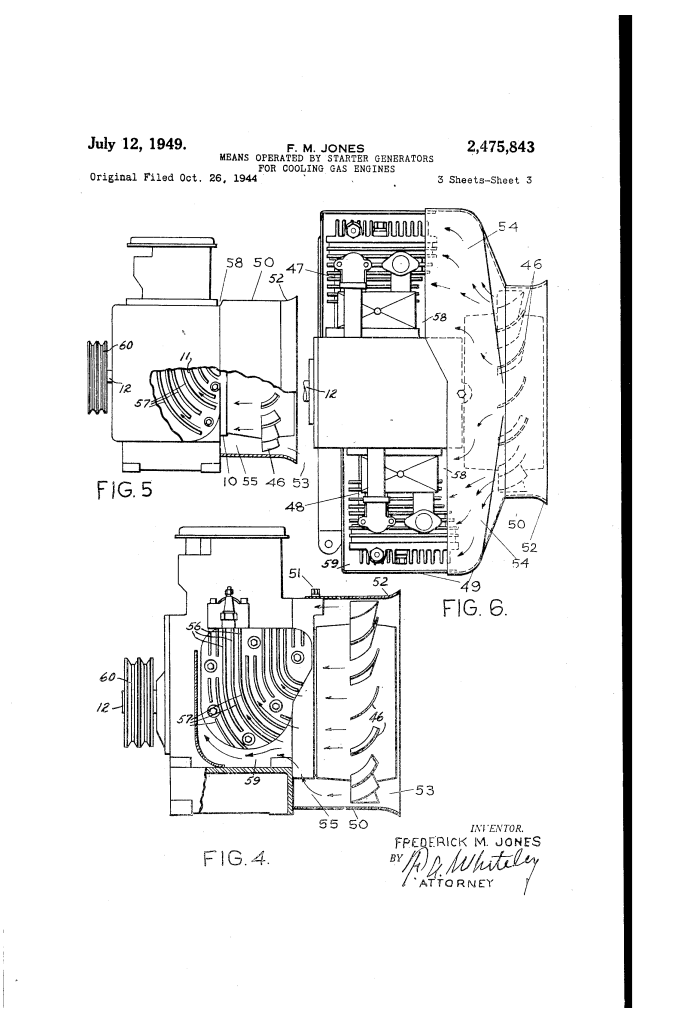
- The Shroud (49): An oval-shaped metal casing that acts as an air tunnel. It creates a pressurized chamber (55) around the blower.
- Directed Flow: The shroud splits the air and forces it through a passageway (59) that underlies the opposed cylinders (47, 48) of the engine.
- Vertical Discharge (58): After the air picks up heat from the engine fins (56), the shroud directs it vertically upward and out of the compartment.
3. Dual-End Crankshaft Balancing
Jones utilized a unique layout to save space and reduce engine wear.
- Rear End: Houses the Pulley (60), which drives the main load (like a refrigeration compressor).
- Front End: Houses the Starter Generator and Blower.
- The Result: This “opposed” layout counter-balances the torque of the main load, preventing the crankshaft from wobbling or wearing out the bearings unevenly. It also makes the entire engine-generator assembly about one-third the length of traditional setups.
Comparison of Cooling Methods
| Feature | Standard Air-Cooled Engine | Jones Integrated System |
| Air Source | Separate belt-driven fan | Built-in Armature Vanes |
| Space Usage | Bulky; requires external pulleys | Ultra-compact; “Hugs” the engine |
| Reliability | Belts can snap or slip | Direct-drive; zero slip possible |
| Generator Cooling | Relies on ambient air | Forced air directly over windings |
| Engine Balance | Front-heavy or unbalanced | Perfectly balanced across crankshaft |
Technical Components of the Cooling System
| Part Number | Component | Function |
| 46 | Blower Vanes | Centrifugal blades that “gather and forward” air. |
| 49 | Shroud | Encloses the vanes to create a pressurized air chamber. |
| 56 | Radiator Fins | Metal extensions on the engine cylinder that release heat. |
| 58 | Egress Openings | Holes in the top of the shroud for hot air to escape. |
| 60 | Power Pulley | The “business end” of the engine, driving the main load. |
Significance
U.S. Patent 2,475,843 was the “missing link” that made portable refrigeration truly reliable:
- Thermal Longevity: By cooling the generator’s insulation, Jones prevented electrical shorts that plagued earlier transport units.
- Compact Footprint: This design allowed the entire power plant to fit into the small “nose” or “undermount” area of a truck.
- Maintenance-Free Cooling: There are no cooling belts to tighten or water pumps to leak, making it ideal for long-haul trucking where a driver cannot stop to perform engine repairs.
Final Insight: Jones’s brilliance lay in his ability to see a machine not as a collection of separate parts, but as a single, breathing organism. In this design, the part that starts the engine also balances the engine, generates its power, and provides its “breath” of cooling air.
