

Mail-Canceling Machine (William Barry, No. 585,074)
The patent by William Barry of Syracuse, New York, describes a comprehensive Mail-Canceling Machine (Patent No. 585,074, 1897). The invention covers numerous improvements designed to create an accurate, reliable, and rapid machine for canceling stamps and postmarking mail-matter. The primary goals were to ensure every piece of mail, regardless of thickness, is stamped properly without missing or jamming, and to automatically stack the mail for easy sorting.
Inventor Background: William Barry
William Barry was an inventor focused on mechanical automation for the postal service and commercial processing. His machine is an ambitious, integrated system designed to bring industrial efficiency and precision to the handling and processing of high volumes of mail, solving a crucial logistical bottleneck of the late 19th century.
Invention and Mechanism
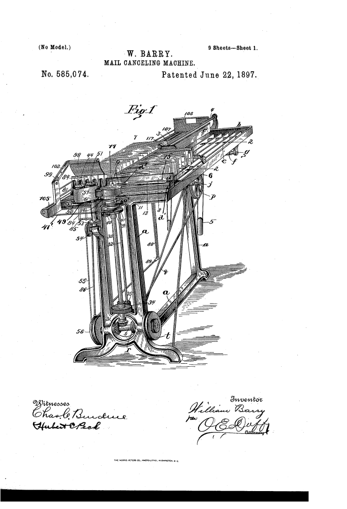
The machine is an integrated system of specialized ways, feeders, printing components, and stacking mechanisms, all synchronized to handle mail continuously.
1. Mail Feeding and Separation
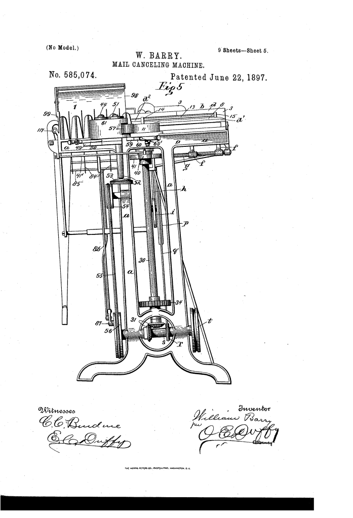
- Reciprocating Feed Floor: The floor of the feedway () is composed of longitudinal bars that are pivoted to arms on a transverse rock-shaft (). This shaft is driven by a cam-and-spring device (
).
- Function: The floor is moved forward slowly by the cam (
) and then snaps quickly back by the spring (
), pushing letters forward without crowding them (the letters are held by inertial fingers
).
- Function: The floor is moved forward slowly by the cam (
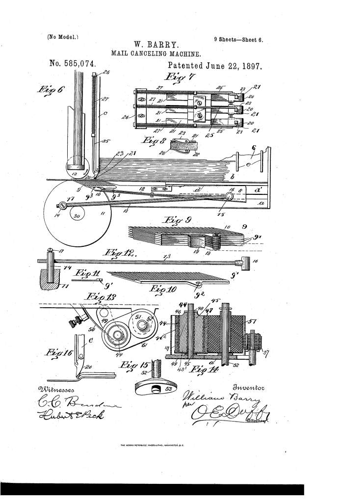
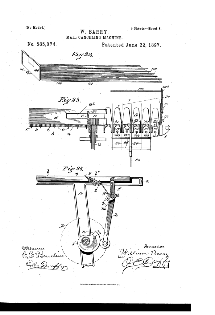
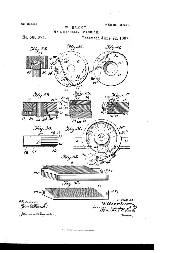
- Sectional Feeder (Key Innovation): A gripping block (9) mounted on a reciprocating plate (8). The block’s inner surface is composed of a plurality of closely arranged needles or fine sharp points inclined in the feeding direction.
- Independent Sections: The block is preferably made of a series of parallel, independent movable plates () that can swing or slide independently.
- Function: This flexible surface ensures the feeder can grip mail-matter of uneven thickness without bending or damaging it, with each section adapting to the contours of the letter.
- Separating Fingers: Rubber strips (21) faced with friction material (22) are yieldingly held across the throat by springs (27).
- Function: These fingers ensure only one letter at a time passes to the printing mechanism, positively holding back adjacent letters.
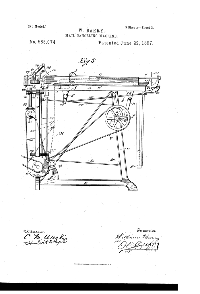
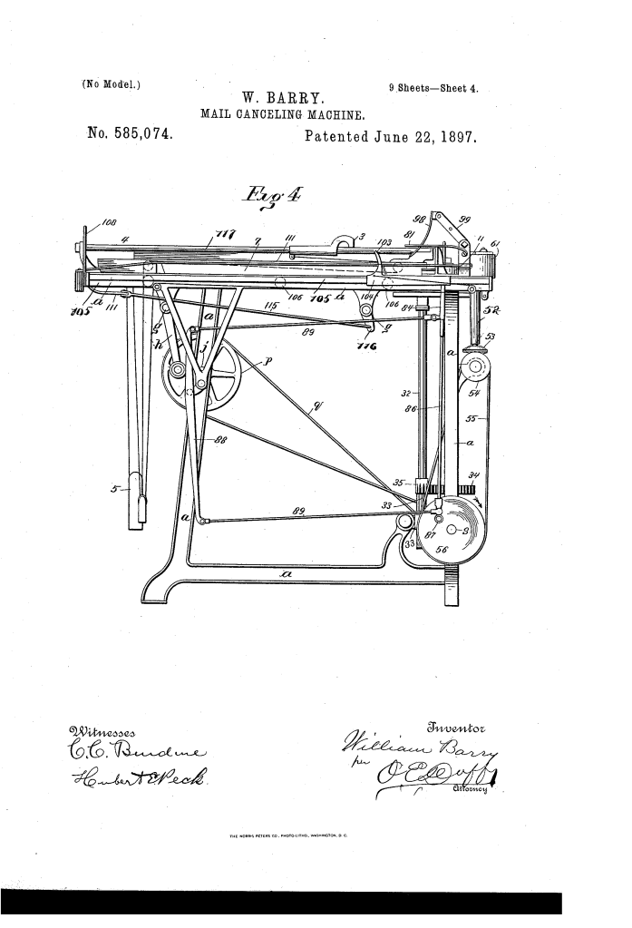
2. Printing and Impression Mechanism
- Tension Relief (Soft Grasp): The impression-roller (
) is mounted in a swinging bracket (33) that is yieldingly pressed against the printing-roll (
) by a spring (37).
- Timed Tension Control (Crucial Innovation): The spring pressure is controlled by a horizontal cam (41) rigid on the printing-roll shaft.
- Function: The cam is timed so that its reduced portion arrives just as the letter enters the rolls, momentarily relieving the spring tension (reducing jar). As the letter enters fully, the cam returns to its full diameter, increasing the pressure to its maximum precisely when the printing type (
) makes contact, ensuring a good impression and accommodating varied mail thickness.
- Function: The cam is timed so that its reduced portion arrives just as the letter enters the rolls, momentarily relieving the spring tension (reducing jar). As the letter enters fully, the cam returns to its full diameter, increasing the pressure to its maximum precisely when the printing type (
- Universal Joint: The impression-roller (
) is mounted on its shaft via a universal joint (shafts 43, 44) to readily yield and accommodate uneven mail surfaces.
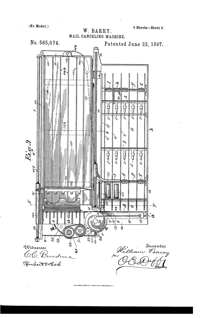
3. Automatic Stacking
- Receiving Way: Letters are shot outward from the printing rolls. The floor is formed with upward inclines/shoulders (82) and a curved guide (81) to direct the letters into a stack.
- Stacking Fingers: A series of vertical fingers (84) mounted on an oscillating pitman (86) move up and forward through slots in the receiving-way.
- Function: These fingers press each letter forward behind the preceding one, keeping the stack tidy.
- Swinging Shield (98): A depending, flexible guard (leather or thin metal) is suspended over the inlet end of the receiving-way.
- Function: The shield rests on the letters and prevents them from “flying up or sidewise” out of the stack when discharged or engaged by the stacker.
- Removable Tray: The receiving-way floor can be a removable tray (107), which is reciprocated by a lever linkage (111, 115, 116) to feed the stack outward, ready for easy removal and sorting.
Concepts Influenced by This Invention
Barry’s machine established foundational principles for high-speed automated processing of disparate materials and precision timing control in industrial machinery.
- Timed Tension Control/Soft Grasp: The mechanism using a cam (41) to dynamically and precisely vary the pressure (tension) between two working rolls (printing and impression) influenced the design of:
- Industrial Feed Mechanisms: Systems that require a soft grasp for initial contact and a firm clamp for actuation, ensuring fragile or delicate materials (like paper or thin plastics) are not crushed during the feeding cycle.
- Self-Contained Dynamic Material Separation: The use of multiple, independently movable sections (plates 9′) in the feeder head to conform to uneven surfaces influenced the design of adaptive grippers, vacuum heads, and sorting mechanisms used in robotics and automation to handle products of irregular geometry or varying thickness.
- Airflow/Inertia Containment: The design of the swinging shield (98) to prevent turbulence or sudden mechanical force from disrupting the stack influenced the design of air guides, deflectors, and stacking enclosures in high-speed printing, labeling, and currency-counting machines.
- Kinematic Synthesis for Stacking: The sophisticated use of eccentric drives and linkages to generate a complex, synchronized motion for the stacking fingers influenced the development of multi-axis product handling systems that push and align goods on production lines.
