
Machine for Shaping Seat-Bars (Enos W. Stewart, No. 365,644)
The patent by Enos W. Stewart of Selma, Alabama, describes a specialized industrial Machine for Shaping Seat-Bars (Patent No. 365,644, 1887). This machine was a significant advancement in the manufacturing of two-wheeled carriages and carts, specifically designed to shape T-rail iron bars into the structural supports for vehicle seats.
Inventor Background: Enos W. Stewart
Enos W. Stewart was an African-American inventor based in Selma, Alabama, during the late 19th century. His work is a prime example of the high-level mechanical engineering occurring in the post-Civil War South. Stewart identified a specific bottleneck in carriage production: the “seat-bar” required complex three-dimensional bending that was difficult to replicate accurately. His invention modernized this process, moving it away from the brute force of a blacksmith’s hammer toward the precision of a multi-action mechanical press.
Key Mechanical Components & Functions
Stewart’s primary innovation was the integration of multiple bending operations into a single movement of a lever.
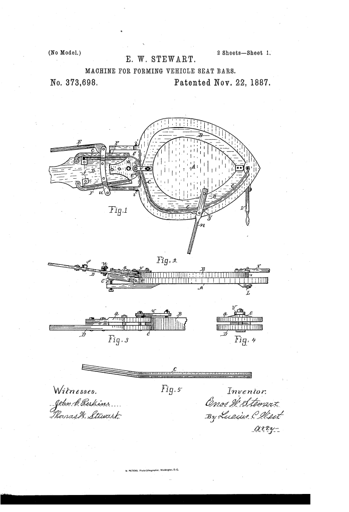
1. The Bed-Plate (A) and Form (B)
The machine is built on a heavy bed-plate (A). Raised sections called forms (B) act as the “mold” around which the iron is bent.
- Dual Forms: Stewart designed the machine with forms on both sides. This allowed for the creation of both right-hand and left-hand seat bars on a single machine, ensuring perfect symmetry for a vehicle.
2. The Clamping Lever (D) (Key Innovation)
The heart of the invention is the clamping lever (D). Older machines used rigid grooves where the hot metal would often become “packered” (wedged) and stuck.
- The Incline (e): As the operator swings the lever, a wedged portion called the incline (e) passes under a metal strap.
- Function: This wedging action automatically tightens the clamp (a) onto the rail flange, securing it for the bend without manual bolting.
3. The Inclined Block (C) (Simultaneous Bending)
- Compound Motion: As the lever (D) swings around the form to bend the rail, it also travels up an inclined block (C).
- Function: This tilts the lever upward as it moves sideways. The result is a lateral tilt of the seat bar, ensuring the bars are angled correctly to support the width of the vehicle seat. This combined two labor-intensive steps into one smooth motion.
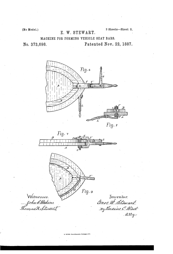
4. The Eye-Forming Mechanism and Release
- Hinge-Eye (r, S, i): At the end of the bed-plate, a secondary set of levers wraps the end of the rail around a vertical pin (x) to create the mounting “eye” or hinge.
- Instant Release (L): After the eye is formed, the operator pulls the release lever (L). This drops the pin (x) below the bed-plate.
- Benefit: Because the clamp (a) is pivoted rather than rigid, the finished bar can be removed instantly without needing a hammer to dislodge it.
Improvements Over the Existing Technology of His Time
| Feature | Old Machines | Stewart’s Machine |
| Removal | Metal wedged into grooves; required a hammer to remove. | Pivoted clamp releases the rail as soon as the lever is swung back. |
| Efficiency | Required separate steps for bending and lateral tilting. | Performs the flange bend and lateral tilt in one swing via the inclined block. |
| Versatility | Limited to one “hand” (right or left). | Dual forms allow for both right and left-hand bars on one unit. |
| Accuracy | Direct pressure could cause bulging. | Uses a pivoted leaf to distribute pressure evenly. |
Significance to Industrial History
Stewart’s machine is a textbook example of mechanical integration. In this era, the goal was to reduce the “manual touch” required between manufacturing steps. By using a simple inclined plane (C) to generate a complex three-dimensional angle, Stewart increased the production speed of vehicle assembly. This logic of “one motion, multiple results” was a critical precursor to the high-efficiency manufacturing that would later define the automotive assembly lines of the 20th century.
