
Machine for Assembling and Disassembling Spring Tensioned Devices, Asa J. Taylor, Patent No. 2,286,242
The patent by Asa J. Taylor of River Forest, Illinois, describes a specialized Machine for Assembling and/or Disassembling the Parts of Spring Tensioned Devices (Patent No. 2,286,242), filed in 1941 and granted in 1942. This mechanical jig was specifically engineered to manage the high-tension valve assemblies of internal combustion engines, particularly those used in Ford automobiles. It provides a safe, tool-free method for compressing heavy valve springs to allow for the insertion of retainers and stirrup brackets without risking injury to the mechanic.
The “Why”
In the 1930s and 40s, engine valves were held under significant spring pressure to ensure they seated correctly against the engine ports. Installing these assemblies was a dangerous and frustrating “pain point”: a mechanic often had to fight the spring’s resistance while simultaneously trying to seat a tiny retainer or bracket. If the spring slipped, it could launch parts at high velocity or pinch fingers. Taylor sought to create a stationary bench machine that could “freeze” the spring in an over-compressed state, making the assembly as easy as dropping a coin into a slot.
Inventor Section: Engineering Philosophy
Asa J. Taylor’s design philosophy centered on Sequential Compression. He realized that the valve assembly needed to be compressed from two different directions at different stages of the process. His machine is a masterclass in cam-actuated logic: a single handle movement dictates which part of the assembly moves and which stays still. This prevented the “chasing” of parts that occurred with traditional hand-clamping tools.
Key Systems Section
1. The Dual-Slide Cam Architecture
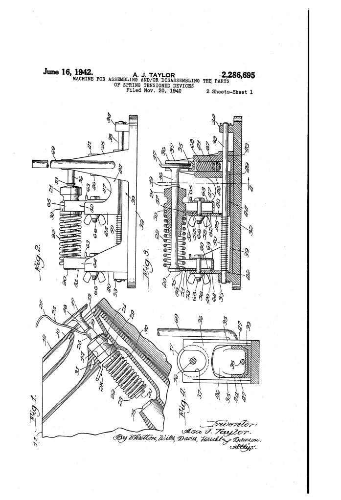
The machine features two independent slides (39 and 44) mounted on a single guide rod (38).
- Mechanical Principle: A central cam block (68) is positioned between the two slides. When the handle (69) is rotated one way, it pushes slide A; when rotated the other way, it pushes slide B.
- Function: This allowed the mechanic to first compress the spring from the “bottom” to install the valve retainer, and then from the “top” to install the temporary shipping bracket.
2. Reversible Universal Saddles
Taylor recognized that engine valves came in various sizes.
- The Innovation: The “cradles” or saddles (51, 52) are U-shaped channels with different-sized recesses at each end.
- User Logic: If a mechanic was working on a large truck valve, they used the wide side (55, 57). For a smaller passenger car valve, they simply flipped the cradle over (56, 58). This modular design eliminated the need for multiple machines.
3. The “Abnormal Tension” Lock
The machine’s primary purpose was to place the assembly into an “abnormal” state—tensioned higher than it would be in the actual engine.
- The Benefit: By over-compressing the spring, the valve stem ($16$) is temporarily “shortened” relative to the bushing ($21$). This creates the necessary clearance to slide the valve assembly into the engine block effortlessly.
- Safety Feature: The cam handle is designed to “lock” in a horizontal position (Fig. 8), holding the massive spring energy securely while the mechanic’s hands are near the moving parts.
4. The Temporary Retainer (The “Handle” Device)
The machine is designed to accommodate a specific “stirrup bracket” and a temporary “retainer device” (25).
- Workflow: The machine holds the spring back so the mechanic can snap on the retainer (25). Once the assembly is placed in the engine, the mechanic simply pulls the handle (27) of the retainer, “firing” the valve into its seated position.
Comparison Table: Hand-Tool Installation vs. The Taylor Machine
| Feature | Standard Valve Lifter (Hand Tool) | The Taylor Machine |
| Stability | Prone to slipping/shifting. | Rigidly mounted base. |
| Operation | Requires two hands to hold tension. | Cam-lock holds tension automatically. |
| Versatility | Usually one tool per valve size. | Reversible saddles for multiple sizes. |
| Safety | High risk of “spring launch.” | Contained slide movement. |
| Complexity | Difficult to align small retainers. | “Drop-in” alignment for parts. |
Significance
Asa Taylor’s machine was a vital contribution to Automotive Service Engineering:
- Standardization of Repair: It allowed garage mechanics to achieve factory-level precision in valve timing and assembly.
- Labor Efficiency: It reduced the time required to “valve” an engine block from hours to minutes, a crucial advancement for the high-volume Ford service centers of the era.
- Ergonomic Safety: It moved the “danger zone” of compressed springs away from the mechanic’s body and into a controlled mechanical track.
