
Locomotive Headlight (William N. Cobbs, No. 1,780,865)
This 1930 patent by William N. Cobbs of Pittsburgh, Pennsylvania, describes an innovative Locomotive Headlight (Patent No. 1,780,865) designed to solve a critical safety issue in early railroading: the inability of fixed headlights to illuminate the track while the train is rounding a curve. By using aerodynamic forces and electrical switching, Cobbs created a system that “looks” around corners and provides audible warnings simultaneously.
1. Wind-Driven Directional Control
The most striking feature of Cobbs’ invention is its reliance on the relative wind to steer the light.
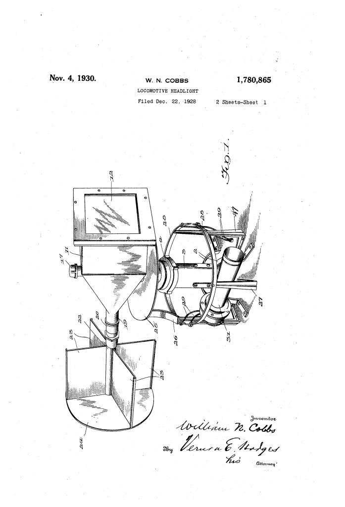
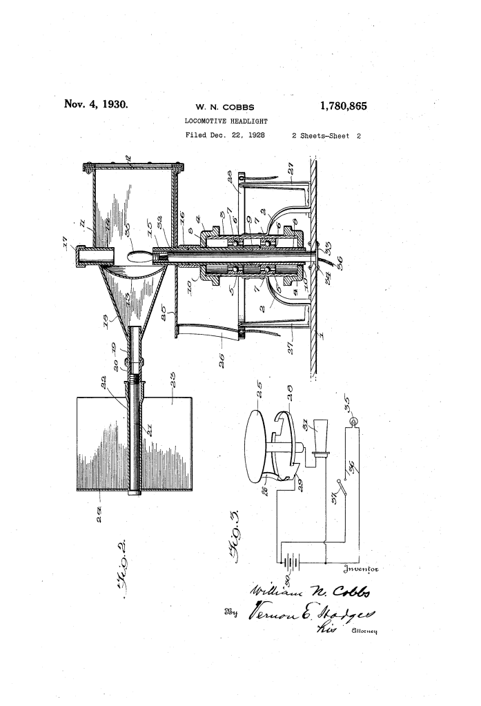
- Pivotal Mounting: The headlight casing (11) is mounted on ball bearings (7) within a sleeve (3), allowing it to rotate freely around a vertical axis.
- Vane Mechanism (23): At the rear of the casing, a series of radiating vanes is mounted on a journal rod (21).
- Aerodynamic Alignment: As the locomotive moves forward, the wind pressure on the vanes acts like a weather vane. When the locomotive enters a curve, the change in the relative direction of the wind (as the locomotive’s body shifts relative to its velocity vector) forces the vanes to turn the headlight casing. This ensures the beam is always directed along the actual path of travel rather than pointing straight off into a field.
2. Automated Audible Warning System
Cobbs integrated a safety signal that triggers automatically whenever the headlight deviates from its center position.
- Segmental Contact Rings (28): Fixed to the stationary bracket are two metal segments.
- Flexible Contact Brush (26): Attached to the rotating headlight base is a brush.
- Circuit Completion: Under normal straight-line travel, the brush sits in the gap between the rings. When the headlight turns to “follow” a curve, the brush slides onto one of the contact rings, completing an electrical circuit with the battery (30) and the horn (31).
- Warning Function: This warns pedestrians or vehicles at crossings around the bend that a train is approaching, even if they cannot yet see the locomotive.
3. Ease of Maintenance: The Tubular Lamp Support
The patent also addresses the practical problem of replacing burnt-out bulbs on a large locomotive.
- Internal Tube (32): The light bulb (35) is not fixed to the casing. Instead, it is mounted on a tube that extends up through the center of the rotating pivot.
- Slide-Out Design: The bulb is smaller in diameter than the support tubes. By disconnecting the plate (33) on the underside of the locomotive’s shelf, a mechanic can simply slide the entire lamp assembly downward and out. This allows for bulb replacement without having to disassemble the heavy, pivoted headlight casing or its aerodynamic vanes.
4. Technical Specifications and Components
| Component | Engineering Purpose |
| Ball Bearings (7) | Minimizes friction so that even light wind pressure can turn the heavy lamp. |
| Bushing (9) | Connects the rotating tubes and serves as the load-bearing surface on the bearings. |
| Sleeve (22) | Allows the vanes to rotate freely to prevent the accumulation of snow or ice, which could unbalance the mechanism. |
| Reflector (13) | Standard parabolic mirror to focus the light from the sliding lamp assembly. |
Historical Context and Safety Statistics
During the late 1920s, railroad safety was a major concern. In 1928 (the year Cobbs filed his application), there were approximately 2,568 fatalities at railroad crossings in the United States. A significant portion of night-time accidents occurred because engineers could not see obstructions on curves until it was too late to brake.
By providing a light that “steered” into the curve, Cobbs’ design directly targeted the “blind curve” hazard. Furthermore, the automatic horn provided a proactive warning—a predecessor to modern automated “ditch lights” and crossing signals used in today’s rail industry.
