
Lockout for Outgoing Calls (Charles V. Richey, No. 1,813,678)
This 1931 patent by Charles V. Richey describes a mechanical and electrical “lockout” device for telephone systems. Its primary purpose is to prevent unauthorized outgoing calls from a specific telephone instrument while still allowing that same instrument to receive incoming calls. This was a sophisticated solution for the era, using a complex arrangement of electromagnets and condensers to distinguish between the electrical signals of a ringing circuit and a talking circuit.
1. The Outgoing Call Barrier
The system works by introducing a physical and electrical break in the standard telephone line.
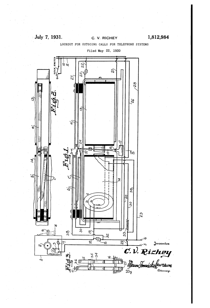
- Line Gap and Condenser (8): A condenser is placed in the line wire (6). Direct current (DC), which is required to signal the operator for an outgoing call, cannot pass through a condenser.
- The Switch (12): Normally, a shunt circuit (bypass) around this condenser can be closed by a switch (12). However, in “lockout mode,” this switch is locked open with a physical key.
- Result: Because DC cannot cross the condenser and the bypass is locked, a user lifting the receiver cannot signal the central office to make a call.
2. Receiving Incoming Calls
The device must automatically bypass the “lockout” only when a call is coming in. It achieves this by utilizing the difference between Alternating Current (AC) used for ringing and Direct Current (DC) used for talking.
- Electro-magnet (13): When an operator sends an AC ringing signal, the current can pass through the condenser (8). Some of this current is diverted to magnet (13).
- Armature (15): The magnet pulls a pivotable armature to the right. This mechanical movement closes several pairs of contacts (a’, b’), effectively creating a temporary bridge across the line gap.
- Subscriber Interaction: When the subscriber picks up the phone to answer, they can now communicate because the armature has mechanically “repaired” the broken circuit.
3. The Neutralizing Magnet (14)
To prevent the lockout from re-engaging during the conversation, Richey used a “bucking” or neutralizing magnet.
- Reverse Windings: Magnet (14) has two main windings (a and b) wound in opposite directions.
- Choke Effect: While the conversation is active, DC flows through both windings simultaneously. Because they are wound in reverse, their magnetic fields cancel each other out (Net Magnetism approx. 0).
- Stability: This ensures the magnet does not pull the armature back prematurely while the parties are still speaking.
4. Automatic Reset (Hanging Up)
The system “relocks” itself automatically once the conversation ends.
- Breaking the Balance: When the subscriber hangs up, the hook switch opens, breaking the circuit for winding (a).
- Return Force: Winding (b) remains energized because it is connected “upstream” of the hook switch. With winding (a) dead, the magnetic balance is lost. Magnet (14) now has a strong pull.
- Duplex Armature: The armature is made of two parts (34, 35). The lighter part is pulled back first, closing a “booster” circuit (c) that provides the final surge of power to pull the entire assembly back to the “Locked” (leftward) position.
Technical Components Summary
| Component | Function |
| Condenser (8) | Blocks DC for outgoing calls; allows AC ringing current to pass. |
| Magnet (13) | The “Unlocker”—uses ringing current to close the talking circuit. |
| Magnet (14) | The “Resetter”—uses DC to pull the armature back to the locked position after a call. |
| Booster Winding (c) | Provides extra mechanical force to ensure the armature fully resets and locks. |
Historical Significance
In the 1930s, telephone service was often billed per call or shared on party lines. Richey’s device provided a “parental control” or “administrative lock” for business or residential phones, ensuring that a phone could be used for emergencies or incoming business without the risk of unauthorized long-distance or toll charges.
