
Locking-Rack for Hats, Coats, and Umbrellas (1896)
U.S. Patent No. 557,076, granted on March 24, 1896, to Lewis H. Latimer (with one-half assigned to Joseph P. McDonough), addresses a major public security problem of the late 19th century: preventing the theft or accidental mix-up of personal property in public venues.
During this era, outer garments, hats, and umbrellas were essential everyday attire, but places like hotels, restaurants, and public halls lacked secure, space-efficient personal storage. Latimer designed a compact, wall-mounted mechanical rack that could simultaneously lock down a hat, a coat, and a cane or umbrella using a single integrated mechanism operated by a single key.
The Innovation: The Single-Bar Multi-Locking System
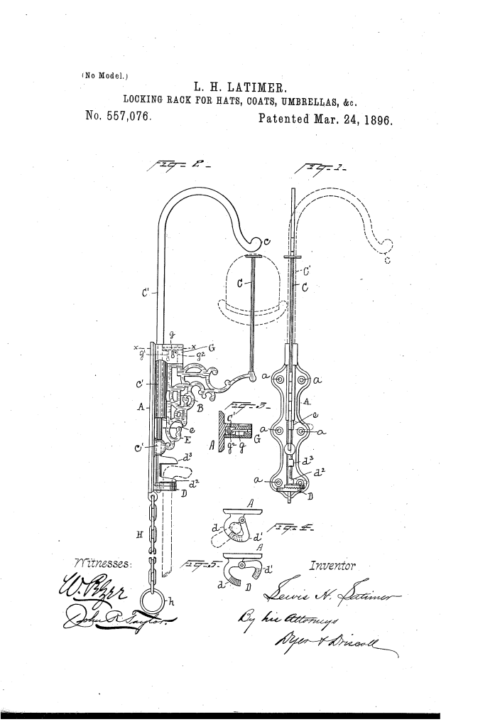
The brilliance of Latimer’s design is its rotational locking-bar (C’). Rather than requiring separate padlocks or complex individual latches for each item, Latimer engineered a central vertical bar that rotates on its axis to physically secure three separate storage components at once.
1. The Hat Keeper
- A curved, “goose-neck” arm (c’) at the top of the rotating bar swings directly over the top of the hat support (C).
- When locked, the arm sits in such close proximity to the top of the hat that the hat cannot be lifted or tilted off the rack.
2. The Coat Hook & Security Chain
- A locking-finger (e) attached to the central bar swings flush against the primary coat hook (E).
- To prevent thieves from stealing a coat by cutting its fabric hanging loop, Latimer included a sleeve chain (H). The chain passes through the coat sleeve and its end ring (h) loops onto hook E; when finger e rotates into place, it physically blocks the ring from slipping off the hook.
3. The Umbrella & Cane Clamp
- The lower holder (D) consists of a rigid arm (d1) and a movable, hinged arm (d2), both featuring interlocking teeth to grip different handle thicknesses.
- To unlock the holder, arm d2 must be lifted vertically to disengage its teeth. When the main locking bar rotates, a lower finger (d3) positioning directly over d2 blocks any upward movement, locking the jaws shut.
- An additional plate (d4) sits directly above the clamp to prevent anyone from sliding the umbrella vertically out of the locked assembly.
How the Apparatus Functions
The process follows a simple, mechanical sequence to ensure ease of use in busy public spaces:
| Step | Action | Mechanical Purpose |
|---|---|---|
| 1. Preparation | Turn the central bar (C’) to the open position (swung away from the wall). | Clears all obstruction from the hat support, coat hook, and umbrella clamp. |
| 2. Loading | Place the hat on support C, hook the coat loop and sleeve chain (H) onto hook E, and slide the umbrella handle into clamp D. | Prepares all three items for simultaneous securing. |
| 3. Engagement | Press the umbrella arm d2 closed against the handle to engage the ratcheted teeth. | Form-fits the clamp to the exact diameter of the cane or umbrella handle. |
| 4. Locking | Rotate bar C’ back toward the wall until the cam-shaped lug (g1) trips the internal spring-bolt (g) of lock G. | Simultaneously blocks the hat, secures the coat chain ring, pins the umbrella arm, and snaps the automatic lock into place. |
Key Mechanical Components
- Bracket-Plate (A) & Bracket (B): The cast base plate mounted directly to the wall via screw-holes (a, a), projecting the working mechanism outward into a minimal footprint.
- Rotational Bar (C’): The master shaft mounted in bearings (c, c) that translates a single rotary movement into multi-point security.
- Spring-Lock (G): An integrated lock box containing a spring-actuated bolt (g). The internal lug (g1) features a sloped cam surface that depresses the bolt upon closing and automatically snaps locked.
- Interlocking Teeth (d1, d2): Dual ratcheted surfaces that prevent horizontal expansion of the umbrella holder unless lifted vertically.
Historical Context and Practical Impact
- Space Efficiency: By consolidating multi-item storage into a single wall-mounted unit, Latimer eliminated the need for large, freestanding coat trees or bulky locker furniture in crowded public venues.
- Property Protection: During the late Victorian era, high-end silk top hats, coats, and decorative walking sticks were prime targets for opportunistic theft. Latimer’s addition of the sleeve chain specifically closed a common exploit (cutting the cloth hanger loop).
- Manufacturing Feasibility: The patent emphasizes cast construction (bracket B and plate A cast as one piece), making it inexpensive to manufacture at scale for mass installation in commercial establishments.
About the Inventor: Lewis H. Latimer
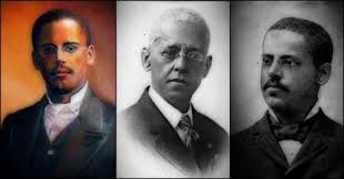
Lewis Howard Latimer was one of the most significant African American inventors and draftsmen of the late 19th and early 20th centuries.
- Inventions: Best known for his landmark 1881 patent on the process for manufacturing carbon filaments for incandescent electric lamps—which made electric lighting practical and affordable—Latimer also invented an early water closet for railroad cars (1874) and a precursor to the modern air conditioner.
- Drafting Expertise: Latimer was a master draftsman who executed the precise patent drawings for Alexander Graham Bell’s telephone patent application. He later served as a key expert witness and chief draftsman for the Edison Electric Light Company.
- Legacy: A charter member of the Edison Pioneers, Latimer’s broad creative range extended from fundamental electrical engineering to practical mechanical solutions for everyday urban life.
Summary of Claims
The patent explicitly claims:
- A partially rotating locking-bar carrying arms that swing into close proximity above a hat-support arm and against a coat-hook, secured by a single lock.
- A hinged umbrella or cane holder controlled by a lower finger on the rotating locking-bar to prevent the holder from opening.
- The integration of a sleeve chain terminating in a ring designed to fit over the coat-hook beneath the locking-finger.
- An umbrella holder featuring rigid and movable arms with interlocking teeth to prevent vertical disengagement when locked.
