
Load Weighing and Totaling Device, Stephen H. Davis, Patent No. 2,332,136
The patent by Stephen H. Davis of Chicago, Illinois, describes a Load Weighing and Totaling Device for Cranes, Hoists, and the Like (Patent No. 2,332,136), filed in 1940 and granted in 1943. This invention provides an integrated hydraulic and mechanical system that allows a crane operator to see the weight of an individual lift while simultaneously tracking the cumulative total of all loads handled during a shift. It solved the problem of manual tallying in high-volume industrial environments like rail yards and shipping docks.
The “Why”
Before 1943, calculating the total weight of cargo moved by a crane was a tedious process of manual bookkeeping. An operator would have to weigh a load (if a scale was even present), record it on paper, and add it up later. This was prone to human error and slowed down operations. The pain point was the lack of real-time data. Davis sought to create a “smart” crane that could perform its own arithmetic, providing immediate feedback on both the current stress on the hoist and the total throughput of the machine.
Inventor Section: Engineering Philosophy
Stephen H. Davis’s engineering philosophy was centered on Kinetic-to-Hydraulic Conversion. He realized that the tension in a hoist cable was a direct, measurable force that could be “tapped” without interrupting the lifting process. His design used the physical “swing” of a weighted lever against the cable to generate fluid pressure. This philosophy ensured the device was self-powered; the very act of lifting provided the energy needed to move the heavy mechanical dials in the cab.
Key Systems Section
1. The Hydraulic “Pressure Tap” Mechanism
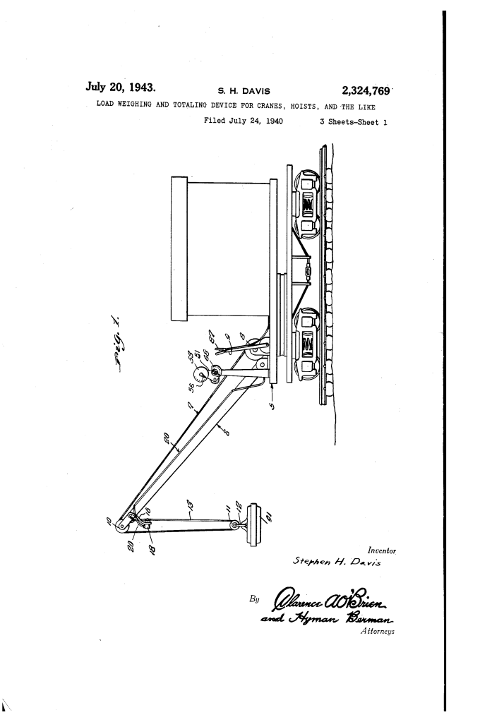
The device begins at the crane boom (6) with a unique S-shaped part (15) and a heavy bar (16).
- Mechanical Principle: As the hoist cable (13) tightens under a load, it pulls against the bar (16), causing it to swing toward the cable flight.
- The “Squeeze” Action: This movement forces a plunger (26) into a cup-shaped fluid housing (18), compressing a diaphragm (23).
- Function: This converts the mechanical pull of the cable into precise hydraulic pressure that is sent down a hose (20) to the operator’s station.
2. The Multi-Dial Totaling Cab
Inside the cab, the hydraulic pressure is translated back into mechanical motion to drive two distinct scales.
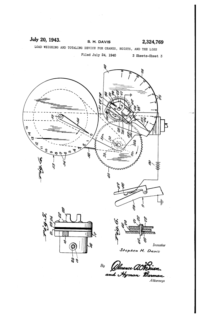
- The Current Load Scale (15): A finger (74) moves across a scale to show the weight of the current item being lifted.
- The Totaling Disk (53): A separate pointer (56) tracks the sum of all loads.
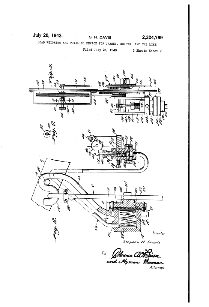
- Engineering Insight: Davis used a mutilated gear (45) and a rack-and-pinion setup to transform the vertical rise of a hydraulic piston into the rotational movement of the clock-like dials.
3. The Electromagnetic “Memory” Clutch
To “total” the weights, the machine needs to know when a load is being intentionally recorded versus when the crane is just moving empty hooks.
- The Innovation: Davis added an electromagnet (82) and a switch handle (87) on the operator’s main control lever (9).
- Operation: When the operator picks up a load, they squeeze the switch. This energizes the magnet, which pulls a dog (80) into engagement with the gear train.
- Function: This “clutches” the totaling dial to the current weight dial. When the load is dropped and the switch released, the current dial snaps back to zero, but the totaling dial stays put, “remembering” the previous weight and adding the new weight on the next lift.
4. Friction Drive and Manual Zeroing
The totaling dial (53) features a friction-drive system (61, 62) and a manual knob (64).
- Purpose: This allows the operator to manually reset the total to zero at the start of a new day or a new train car without forcing or damaging the internal gear teeth. It provides a “slip” point that protects the delicate clockwork of the totaling mechanism from mechanical shocks.
Comparison Table: Standard Crane vs. Davis-Equipped Crane
| Feature | Standard 1940 Crane | Davis-Equipped Crane |
| Weight Tracking | Manual tallying/Guesstimation. | Automatic real-time totaling. |
| Power Source | None/External electricity. | Self-powered by cable tension. |
| Operator Feedback | Visual “load feel” only. | Dual-dial precision interface. |
| Error Rate | High (human math errors). | Low (direct mechanical addition). |
| Safety | Risk of overloading unknown. | Instant visibility of hoist stress. |
Significance
Stephen H. Davis’s invention was a pioneer in Industrial Telemetry:
- Logistics Efficiency: It allowed rail companies and shipping lines to know exactly how much weight was on a car or ship the moment it was loaded, streamlining billing and logistics.
- Safety Engineering: By providing a clear weight readout, it significantly reduced “boom collapse” accidents caused by lifting loads that exceeded the crane’s rated capacity.
- Precursor to Digital Scales: The logic of using a “trigger” (the electromagnetic switch) to record a discrete event into a cumulative memory is the mechanical ancestor of modern digital “Total/Accumulate” buttons on electronic scales.
Next Step: This device relied on maintaining a perfect hydraulic seal over long periods of heavy vibration. Would you like me to explain how the helical take-up spring (23) in the pressure housing helped “balance” the scales to ignore the dead weight of the hook and cable?
