
Linearly Polarized Monopulse Lobing Antenna (1962)
U.S. Patent No. 3,063,049, granted on November 6, 1962, to Kenneth C. Kelly and assigned to Hughes Aircraft Company, describes an advanced planar antenna designed for “monopulse” or “silent” lobing. This invention was a significant leap forward in radar technology, allowing for precise directional tracking while maintaining a low-profile, “flush-mounted” design suitable for high-speed aircraft and missiles.
The Problem: Bulky and Complex Tracking Feeds
Before this invention, antennas capable of tracking objects (lobing) usually required complex setups:
- Aperture Blocking: Standard systems used a parabolic dish with four separate feed horns. These horns sat in front of the dish, physically blocking some of the signal and creating aerodynamic drag.
- Heavy Circuitry: Combining the signals from these four points required extensive and heavy waveguide plumbing.
- Aerodynamics: Large “protruding feeds” were unsuitable for the streamlined surfaces of modern aircraft.
The Innovation: The Segmented Radial Waveguide
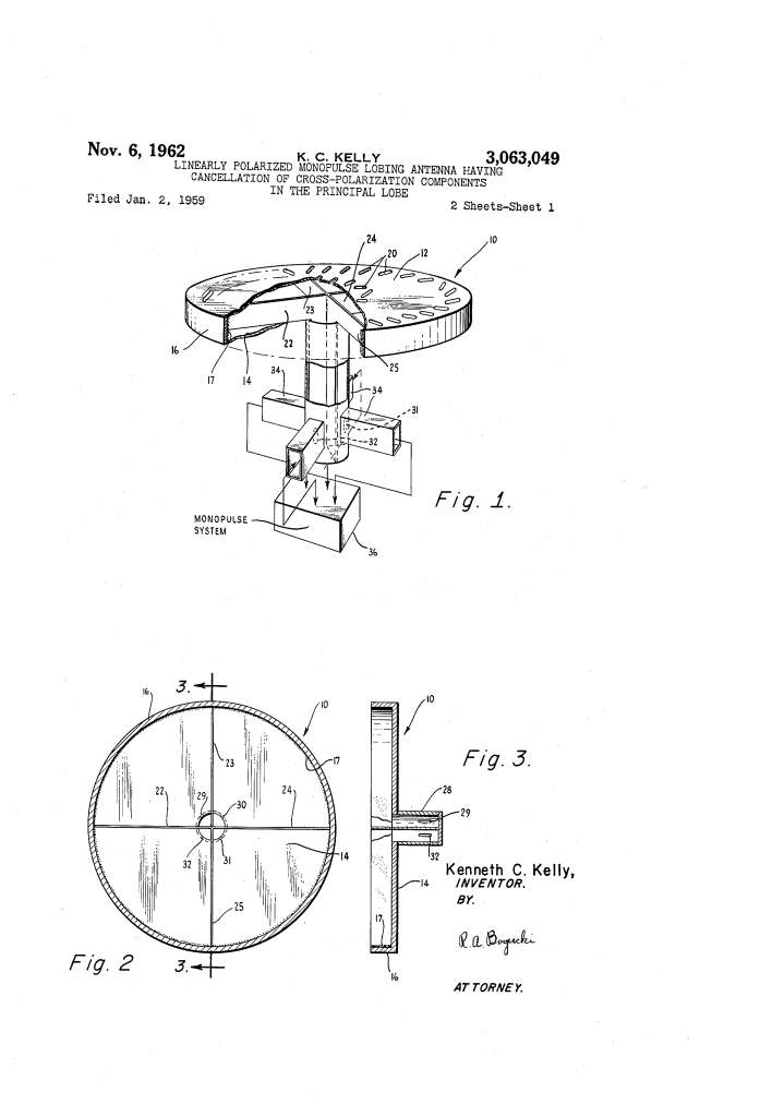
Kelly’s antenna uses a radial waveguide (10)—essentially two parallel conductive plates—that can be mounted flush with the skin of an aircraft. The magic lies in how the internal space is divided and how the radiating slots are oriented.
1. Quadrant Division
The interior of the waveguide is divided into four equal quadrants by conductive septa (22-25). These metal walls act as partitions that allow each quadrant to support its own “partial mode” of electromagnetic energy. By controlling the phase of the energy fed into each quadrant, the antenna can electronically “steer” its focus without moving parts.
2. The Radiating Slots (20)
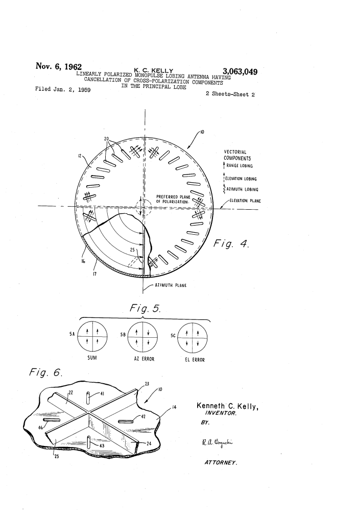
The top plate of the antenna features rings of slots. Their design is critical for linear polarization:
- Matching Inclination: All slots are tilted at a specific angle (e.g., 45 degrees) relative to the circle they sit on.
- Opposing Attitudes: While the angle is the same, the direction of the tilt (the attitude) is flipped in adjacent quadrants.
- Cross-Polarization Cancellation: This clever geometry ensures that unwanted “cross-polarized” signals (noise) from one quadrant are canceled out by the opposing signals in the next, resulting in a very “clean” primary beam.
How Lobing Works
The antenna derives “error signals” (how far left/right or up/down a target is) by combining the energy from these four quadrants in different ways:
| Mode | Operation | Result |
| Sum Signal | All four quadrants added together. | A single, powerful “pencil beam” for ranging. |
| Azimuth Error | Left quadrants vs. Right quadrants. | Tells the system if the target is to the left or right. |
| Elevation Error | Top quadrants vs. Bottom quadrants. | Tells the system if the target is above or below. |
Key Advantages
- Flush Mounting: The antenna can be built into the wing or fuselage of an aircraft without any protruding parts, preserving aerodynamics.
- Lightweight: By integrating the “feed” system directly into the waveguide structure, it eliminates the need for heavy external plumbing.
- Silent Lobing: Because it processes all signals simultaneously (monopulse), it can track a target without having to physically “wiggle” the beam, making it harder for the target to detect it is being tracked.
Significance
Kelly’s design was a pioneer in planar array technology. It moved radar away from the “spinning dish” era toward the flat, electronically steered arrays used in modern stealth aircraft and advanced satellite communications.
