
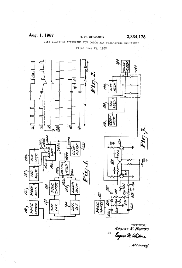
Line Blanking Apparatus for Color Bar Generating Equipment (1967)
U.S. Patent No. 3,334,178, granted on August 1, 1967, to Robert R. Brooks, describes a specialized electronic blanking circuit designed to eliminate visual distortion and line displacement in television color bar test generators. Robert Brooks, an engineer based in Willingboro, New Jersey, developed the system for the Radio Corporation of America (RCA) to solve an alignment defect encountered in broadcast studio equipment.
This invention addressed an operational challenge in color television broadcasting: the transition toward running video signal sources using only composite blanking and synchronizing signals, while eliminating the dedicated cabling and distribution amplifiers previously needed for horizontal and vertical drive lines.
The Problem: Half-Line Distortion in Color Test Patterns
A color bar generator is an essential diagnostic instrument used by television stations to calibrate colorplexers and studio monitors. Following Electronic Industries Association (EIA) standards, it generates seven vertical color bars across the screen arranged in descending order of luminance: white on the far left, followed by yellow, cyan, green, magenta, red, and blue on the far right.
In older studio configurations, each active scan line was triggered directly by the trailing edge of dedicated horizontal drive pulses. When engineers streamlined facilities by removing horizontal and vertical drive signals and triggering studio equipment directly from composite blanking signals instead, an unexpected flaw emerged:
- Odd-Line Interlace Conflict: Standard television broadcasting relies on an interlaced raster scan. Because of the odd-line interlace structure, the first scan line in alternate fields begins midway across the screen rather than at the left edge.
- Pattern Displacement: On that initial half-line scan, the trailing edge of the blanking pulse fires at mid-screen. As a result, color bars were displayed completely out of place—such as a white bar appearing in the middle of the screen where green ought to be.
- Test Distortion: This misaligned half-line gave the false appearance of equipment failure, failed EIA performance specifications, and corrupted waveform diagnostics when monitors were underscanned or repositioned for testing.
The Innovation: Asymmetric Differentiation and Line Blanking
Brooks solved this issue by designing an automated gating system that detects the precise conclusion of the vertical blanking interval and actively suppresses the first line (or half-line) of video information in each field before it reaches the colorplexer unit.
The circuit splits the incoming composite blanking signal across two parallel differentiating paths with radically different time constants to drive a high-speed bistable multivibrator.
Why Asymmetric Differentiation?
- Long Time-Constant Path: Employs a time constant roughly 1,000 times longer than the secondary path. It senses the trailing edge of the broad vertical blanking component and switches the flip-flop multivibrator into a suppressing state right as the field scan begins.
- Short Time-Constant Path: Sharpens the narrow horizontal blanking pulses into clean, narrow trigger spikes. Passed through a slight delay circuit (approximately 0.1 microsecond), it resets the multivibrator at the conclusion of the very next horizontal blanking pulse.
- Clean Line Suppression: The resulting multivibrator pulse generates an exact suppression window that blocks the flawed initial line without clipping or distorting any of the remaining 262 active lines of the field.
Key Circuit Components
The apparatus integrates standard pulse-shaping stages to control the flow of color test signals:
| Component | Schematic Callout | Function in Apparatus |
| Composite Signal Source | 110 | Delivers composite blanking waveforms containing both horizontal line and vertical field pulses. |
| First Differentiating Circuit | 120 (Capacitor 300, Resistor 304) | Long time-constant filter that isolates the energy of the vertical blanking pulse trailing edge. |
| Clipping Circuit | 130 (Diode 314, Resistors 308-312, -V) | Clips the differentiated waveform to deliver a single negative-going trigger pulse to the flip-flop. |
| Second Differentiating Circuit | 140 (Capacitor 302, Resistors 306, 308) | Short time-constant network creating sharp impulses from horizontal blanking transitions. |
| Delay Circuit | 150 (Resistor 316, Capacitor 318) | Imparts an approximate 0.1 microsecond delay to ensure stable multivibrator resetting. |
| Bistable Multivibrator | 100 (Transistors 322, 326) | Two-state flip-flop that generates the gating pulse across interval Z to blank the top line. |
| Color Multivibrators | Green (170), Red (180), Blue (190) | Pulse generators operating at harmonically related frequencies (1x, 2x, 4x) to form the EIA color bar spectrum. |
| Signal Gating Circuit | 160 | Shunt or series gate that blocks color pulses during interval Z and passes them during intervals X and Y. |
| Colorplexer Unit | 200 | Studio encoder combining primary color signals into the composite NTSC color broadcast signal. |
How the Apparatus Functions
The line blanking circuit executes a rapid sequence during the critical microsecond transition from vertical retrace to active picture scanning:
| Step | Action | Operational Purpose |
| 1. Signal Reception | Composite blanking from source 110 splits simultaneously into differentiating circuits 120 and 140. | Feeds field and line timing components into separate timing filters. |
| 2. Gating Initiation | Differentiating circuit 120 and clipper 130 detect the trailing edge of vertical blanking and trigger input 100a. | Flips multivibrator 100 into its second stable state, opening the blanking window. |
| 3. Signal Suppression | Multivibrator output 100c activates gating circuit 160 across duration interval Z. | Disconnects color multivibrators 170, 180, and 190, suppressing the misaligned first line. |
| 4. Delayed Reset | Differentiating circuit 140 and delay 150 feed a delayed horizontal trigger pulse l to terminal 100b. | Resets multivibrator 100 to its initial stable state coincident with the next horizontal line start. |
| 5. Video Transmission | Gating circuit 160 returns to its normal conducting state across intervals X and Y. | Passes all subsequent lines into colorplexer input 200a to form an undistorted color bar pattern. |
Technical and Broadcast Impact
Robert R. Brooks’s invention provided immediate operational and financial advantages for television networks and manufacturing facilities during the height of the 1960s color television transition:
- Reduced Studio Cabling: Broadcasters could decommission dedicated horizontal and vertical drive distribution amplifiers and miles of coaxial transmission cables, cutting maintenance and infrastructure overhead.
- Standardized EIA Alignment: Ensuring the complete elimination of displaced color bars allowed broadcast monitors, tape recorders, and transmitters to meet rigorous EIA colorimetry and sync alignment tolerances.
- Circuit Stability: By utilizing an adjustable delay circuit (150), technicians could widen the blanking interval slightly beyond one line, improving the noise margin and switching stability across tube and solid-state television systems alike.
About the Inventor: Robert R. Brooks
Robert R. Brooks was an electrical engineer who contributed significantly to television broadcasting and signal processing at the Radio Corporation of America (RCA) in Camden and Princeton, New Jersey. Working during the era when RCA set the global engineering benchmark for NTSC color broadcasting, Brooks specialized in precision timing networks, synchronizing waveform generation, and video distribution systems. His circuit designs helped resolve real-world studio integration challenges as broadcasting networks moved toward automated, simplified master control systems.
Summary of Claims
The patent explicitly claims:
- A line blanking apparatus for color bar generators triggered by composite blanking signals, utilizing two differentiating circuits with distinct time constants to switch a bistable multivibrator.
- Switching the multivibrator to its second state via the first differentiating circuit and a clipping stage upon the trailing edge of the vertical blanking pulse.
- Returning the multivibrator to its initial state using the second differentiating circuit and a delay network upon the delayed trailing edge of a subsequent horizontal blanking pulse.
- Using the resulting multivibrator pulse to control a gating circuit (either a series gate or a normally inhibited shunt gate) to delete at least the first line of each field from the generated color bar pattern while passing all remaining lines to the colorplexer.
