
Lawn Sprinkler (1898)
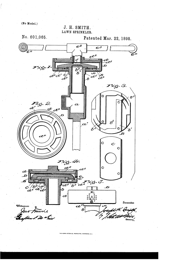
U.S. Patent No. 601,065, granted on March 22, 1898, to Joseph H. Smith, describes an efficient, durable lawn sprinkler designed to distribute water across expansive grounds using internal hydraulic drive.
Late 19th-century mechanical sprinklers often suffered from complex gear assemblies, excessive moving components, and frequent clogging. Smith, an inventor based in Washington, D.C., addressed these mechanical failures by designing a streamlined, self-propelled unit that eliminates external linkages, relying entirely on the kinetic energy of pressurized water to drive a single moving rotary housing.
The Core Design: The Enclosed Internal-Drive System
The core of Smith’s design lies in its concentric head assembly. An internal stationary head directs incoming pressurized water through opposed lateral ports, driving the enclosing rotary head like a miniature water turbine before the water is atomized and cast across the lawn.
- The Stationary Distribution Head (B)The non-moving core of the unit is mounted directly to the main water supply via a threaded pipe section (b).
- The underside of this head contains a transverse groove (b1) and a cutout channel (b2) enclosed by a flat base plate (C).
- Two lateral discharge ports (b3) face in opposite directions, funneling the full force of the incoming water into dual high-velocity jets.
- The Rotary Turbine Housing (D)Enclosing the stationary head is a circular, free-spinning outer drum consisting of a bottom plate (d1), a perimeter rim (d), and a threaded removable top cap (d2).
- The inner face of the bottom plate features a circular ring of inclined grooves (d6) acting as turbine buckets.
- Water jetting from the stationary ports strikes these angled bucket surfaces, driving the rapid rotation of the outer housing through hydraulic impulse.
How the Apparatus Functions
The unit operates through a continuous, closed fluid pathway that couples rotation with distribution:
| Step | Action | Functional Purpose |
| 1. Ground Anchoring | The supporting rod (a1) is driven into the soil, and a standard hose is threaded to the T-joint (a). | Secures the sprinkler firmly in place against water pressure and mechanical torque. |
| 2. Fluid Intake | Pressurized water enters through pipe section (b) and fills the internal channel (b2). | Directs the incoming volume into the stationary distributor withoutLawn-Sprinkler (1898) |
U.S. Patent No. 601,065, granted on March 22, 1898, to Joseph H. Smith of Washington, District of Columbia, details an efficient, durable rotary lawn sprinkler engineered to distribute water across expansive surface areas while minimizing mechanical wear.
Late 19th-century mechanical irrigation devices frequently suffered from complex, fragile gear assemblies that easily clogged with sediment or broke under standard water pressure. Smith’s invention solved this by eliminating complex linkages entirely, relying on a water-driven internal turbine design with only a single moving element: the rotary head.
The Core Design: Internal Reaction Turbine
The operational heart of the Smith sprinkler relies on an enclosed stationary manifold that channels pressurized water across internal “buckets” to drive rotation without external gears.
- Stationary Water Director (B)Mounted directly to the water-supply intake, the stationary head directs incoming pressurized water through an internal channel (b2) and out via two oppositely positioned lateral outlet ports (b3). The base of this channel is sealed with a flat plate (C) integral to the supply pipe, forcing water to exhaust tangentially at the bottom face of the head.
- Rotary Drum and Turbine Buckets (D)Enclosing the stationary head is a circular rotating housing featuring a bottom plate (d1) lined with a ring of inclined grooves (d6) that function as reaction buckets. As water streams out of the stationary ports (b3) in opposite directions, it strikes these angled buckets, driving the entire housing to spin smoothly on the pipe-section boss (d5).
Distribution Modes
Smith designed two distinct configurations to adapt the sprinkler for either compact residential yards or wide-area grounds:
| Configuration | Structural Setup | Functional Purpose |
| Perforated Rim (Direct) | Water escapes directly through rim perforations (e) and a pluggable vent hole (e1). | Provides a concentrated, close-range perimeter spray suitable for standard lawns. |
| Extended Lateral Spray Arms | Water travels over the tapered top of the stationary head, through top opening (d2), into a T-joint (e2) with dual pipes (e3) and opposed nozzles (e4). | Throws high-pressure spray over a significantly broader operational radius. |
Key Technical Components
- Supporting Ground Rod (a’): Anchors the assembly firmly into the turf, resisting vibration and reactionary torque during high-pressure operation.
- Inlet T-Joint (a): Connects the external garden hose line directly to the primary vertical supply pipe.
- Stationary Flow Channel (b2, b3): Divides the single supply stream into two counter-balanced thrust jets to induce rotary motion.
- Removable Drum Top (d2): Threaded onto the outer rim (d3), granting immediate access for maintenance and sediment clearance without unseating the base.
- Tapered Deflector (f): A machined depression in the upper face of the stationary head designed to optimize upward fluid flow toward the extended lateral sprayers.
Historical and Mechanical Impact
Joseph H. Smith’s mechanism reflects the late Industrial Era turn toward simplified, fluid-powered mechanical automation.
- Elimination of Gear Trains: By harnessing hydro-kinetic impulse directly against inclined grooves, the design reduced mechanical failure points to zero exterior gears.
- Operational Longevity: With only one moving component (rotary head D), friction and particulate fouling were reduced, ensuring long service life under sediment-heavy municipal water supplies.
- Modular Adaptability: The interchangeable choice between direct rim-perforation misting and wide-radius pipe nozzles allowed groundskeepers to customize water distribution to fit property dimensions.
About the Inventor: Joseph H. Smith
Joseph H. Smith operated out of Washington, D.C., during a pivotal era of municipal infrastructure modernization at the turn of the 20th century. His contributions to fluid distribution technology addressed the growing need for practical, domestic and civic utility hardware that was both economical to manufacture and reliable for everyday maintenance.
Summary of Claims
The patent explicitly claims:
- A rotary circular sprinkler head driven by water impinging against bucket grooves in its floor from an enclosed stationary head.
- A stationary head with an under-side channel terminating in two lateral, oppositely directed discharge ports.
- The combination of a central water-inlet pipe passing through a sealed plate directly into the internal drive channel.
- An optional dual lateral-pipe arm assembly equipped with opposed terminal sprayers to maximize sprinkling coverage.
