
Lawn Sprinkler (1897)
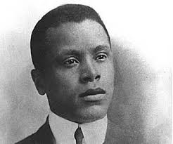
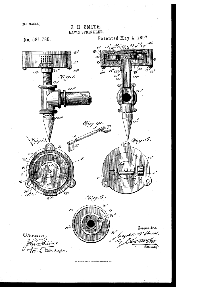
U.S. Patent No. 581,785, granted on May 4, 1897, to Joseph H. Smith, describes an improved mechanical lawn sprinkler designed to provide efficient, continuous rotational spray using water pressure. Joseph H. Smith, an inventor based in Washington, District of Columbia, focused his design on mechanical simplicity, low-pressure operation, and long-term durability.
This invention addressed common shortcomings in late 19th-century irrigation equipment: high friction, mechanical complexity, clogging, and the requirement of high water pressure to achieve rotation. Smith engineered a self-actuating internal drive mechanism that allowed the sprinkler head to spin reliably even under low water supply forces without wasting water.
The Core Mechanism: Alternating Rock-Shaft Blades
The central innovation of the Smith sprinkler is an enclosed, self-tripping dual-blade drive assembly. Rather than relying on simple spray reaction force (like a standard free-spinning nozzle), the unit uses a mechanical rock-shaft carrying two offset wings that alternate positions inside an internal circular raceway.
- The Rocking Wing Action: Two blades (E, E) are mounted at right angles (90 degrees) to each other on the ends of a central shaft (f) mounted in the rotary cover.
- The Tripping Lug: A fixed curved lug (f3) positioned on the floor of the circular passageway trips the active blade upward into a recessed housing pocket (f2).
- Continuous Engagement: As the upward blade retracts into its pocket, the rock-shaft automatically lowers the secondary blade into the water stream just past the flow barrier, capturing the continuous hydraulic force of the pressurized water to sustain rotational momentum.
Key Mechanical Components
The assembly consists of a stationary base and an outer revolving housing that work in tandem:
| Component | Patent Callout | Functional Role |
| Supply Pipe & Base | a, a1, a2 | Delivers pressurized water through a T-joint while anchoring the unit into the lawn via a tapered stake. |
| Stationary Head | B, b, b1, b3 | A fixed disk with concentric inner and outer flanges forming a circular channel (b) with dedicated inlet and outlet ports. |
| Channel Cover Disk | C, c1, d, d1 | Fastened over the inner flange; features a widened sector (d) and a depending stop flange (d1) to direct water flow around the track. |
| Rotary Housing | D, e, e1, e4 | The outer spinning cylinder enclosing the stationary head, pivoting on an upper center stud (e3). |
| Perforated Spray Plate | e5, g | A series of discharge apertures along the outer rim that distribute the water into a broad, even spray as the head revolves. |
| Alternating Rock-Shaft | E, f, f2, f3 | Houses the angled drive blades that flip sequentially when striking the floor lug (f3) to maintain continuous rotation. |
How the Apparatus Operates
The device converts direct water pressure into rotary distribution through a four-stage internal cycle:
- Intake and Channeling: Pressurized water enters through the supply pipe (a), passing through inner port (b3) directly into the circular channel (b).
- Impulsion: The flowing water strikes whichever blade (E) is currently lowered into the raceway, pushing against it and driving the entire outer rotary casing (D) around the central axis.
- Mechanical Tripping: As the active blade completes its sweep near the closed barrier (d1), it contacts the upwardly projecting curved lug (f3), rocking the shaft (f).
- Blade Reset & Discharge: The rocking motion lifts the leading blade into pocket (f2) while plunging the trailing blade into the open stream, sustaining rotation while the water exhausts through the outer spray holes (e5).
Historical and Practical Significance
Joseph H. Smith’s 1897 design represented a distinct leap in municipal and domestic lawn care mechanics at the turn of the century.
- Low-Pressure Efficiency: Because the driving blade directly intercepts the enclosed channel stream, the sprinkler functions effectively on low water pressure without stalling.
- Reduced Wear and Tear: Enclosing the drive assembly inside a protective outer box shielded the moving pivot points from dirt, sand, and yard debris.
- Even Water Distribution: By combining mechanical rotation with a multi-hole spray plate, the apparatus ensured broad, non-pooling coverage across lawns and gardens.
About the Inventor: Joseph H. Smith
Joseph H. Smith was an inventor residing in Washington, D.C., active during the rapid expansion of American municipal water systems in the late 19th century. His contributions focused on practical fluid handling and mechanical engineering, developing utilitarian devices that maximized mechanical leverage and minimized manufacturing complexity.
Summary of Claims
The patent explicitly claims:
- A stationary head featuring dedicated water inlet and outlet ports combined with a concentric circular passageway.
- A revolving outer casing containing a rock-shaft with drive blades mounted at right angles to each other.
- The alternating mechanical immersion of blades into the water flow path triggered by an internal stationary tripping lug.
- A multi-flanged channel disk that guides fluid pressure directly against the internal drive mechanism before discharging through external spray apertures.
