
Lawn Mower Attachment, Samuel J. Hines, Patent No. 1,911,278
The patent by Samuel J. Hines of Alexandria, Louisiana, describes a Lawn Mower Attachment (Patent No. 1,911,278). This invention is a retractable sod-trimming and trenching tool that mounts directly to a standard push mower, allowing the operator to edge sidewalks and garden paths using the mower’s own weight as the primary cutting force.
The “Why”
In the early 1930s, maintaining a “manicured” lawn edge required a separate, labor-intensive process involving hand-held spades or specialized heavy machinery. Hines identified that the dead weight of a standard lawn mower was an untapped resource. He sought to solve the “lateral canting” (tilting) problem common in manual edgers by leveraging the mower’s wide wheelbase as a stable platform, while creating a mechanism that could “disappear” when the mower was used for standard grass cutting.
Inventor Section: Samuel J. Hines
Samuel J. Hines was a Black inventor in the Jim Crow South, a region where agricultural and mechanical ingenuity were often born out of economic necessity. His engineering philosophy focused on multi-functionality and mechanical ergonomics. At a time when specialized landscaping tools were a luxury, Hines’s invention transformed a single-purpose machine (the mower) into a dual-purpose maintenance suite. His design is particularly clever for its “over-center” locking lever, a sophisticated mechanical principle that ensures the tool stays engaged without the operator needing to apply constant downward pressure.
Key Systems Section
1. The Compound Articulated Lever (Deployment System)
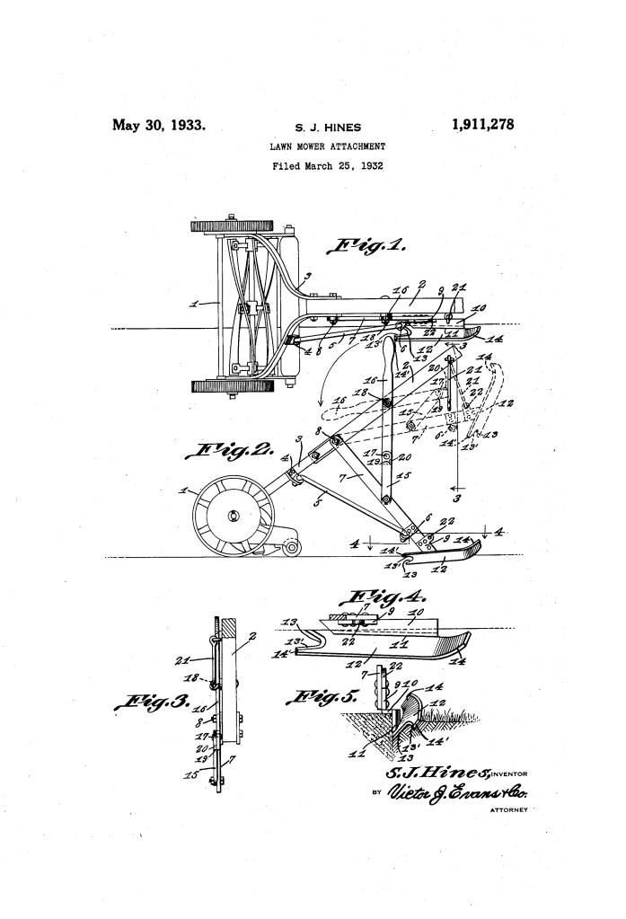
The attachment is controlled by a two-section operating lever (15, 16).
- Modern Translation: A folding linkage with a mechanical stop.
- When the sections are aligned, an angle finger (20) locks into a notch (19), creating a rigid pillar that holds the blade in the ground. To retract the tool, the operator “breaks” the joint, folding the sections to lift the blade.
2. The Multi-Axial Shovel Blade (Cutter)
The cutting element (12) is not a simple flat blade; it is an “angularly disposed elongated shovel.”
- Modern Translation: A contoured plow blade with a compound bevel.
- The blade features a notched leading edge (13, 13′) to slice through tough sod and a rounded rear “moldboard” (14) that automatically directs the displaced earth onto the walkway for easy cleanup.
3. The Depth-Gauge Assembly
A flat plate (10) is associated with the blade to regulate how deep the trench is cut.
- Modern Translation: An adjustable depth skid or “limit switch.”
- This plate rides along the surface of the lawn, ensuring that the trench remains uniform regardless of how hard the operator pushes.
Comparison Table
| Feature | Standard Edging (1930s) | Hines’s Innovation |
| Power Source | Manual upper-body strength. | Gravity and the mower’s total mass. |
| Stability | Highly unstable; prone to “wobble.” | Balanced by the mower’s four-wheel footprint. |
| Tool Management | Required carrying multiple heavy tools. | Integrated “permanent” attachment. |
| Earth Removal | Required manual shoveling after cutting. | “Self-clearing” blade throws soil onto the path. |
Significance Section
- Integrated Landscaping: A direct precursor to modern “combi-system” lawn tools where one power head operates multiple attachments.
- Ergonomic Leverage: Used the mower’s handle as a long-arm lever, reducing the $Torque = rF$ required by the human operator to penetrate hard Louisiana clay.
- Waste Management: The inclusion of a debris-deflector (the rounded rear end of the blade) foreshadowed modern mulching and side-discharge mower decks.
