
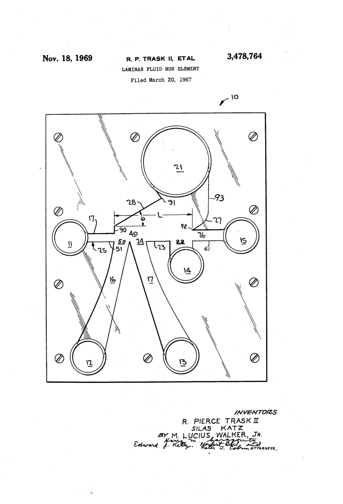
Laminar Fluid NOR Element (1969)
U.S. Patent No. 3,478,764, granted on November 18, 1969, to Roland Pierce Trask II, Silas Katz, and M. Lucius Walker, Jr. (assigned to the United States of America as represented by the Secretary of the Army), addresses a critical energy and packaging bottleneck in fluidic computing: operating digital logic gates at ultra-low pressures entirely within a laminar flow regime.
Fluidic devices—or fluid amplifiers—perform digital and analog computations without any moving mechanical parts, making them immune to extreme heat, shock, vibration, and nuclear radiation. However, earlier fluidic NOR logic elements were turbulent devices that demanded high operating pressures, consumed substantial power, and generated disruptive back-pressures that made stacking multiple gates into complex circuits nearly impossible. Trask, Katz, and Walker, working through the Harry Diamond Laboratories and academic partnerships, developed an aligned, atmospheric-vented NOR element that operates reliably on a pressure supply of only a few inches of water.
The Core Innovation: Pure Laminar Logic
Prior fluidic gates required forceful, turbulent jets to achieve reliable signal switching. That high velocity created localized pressure buildups, turbulent dissipation, and packaging bulk that prevented high-density circuit integration.
The inventors solved this by designing an architecture specifically engineered to maintain stable laminar flow across the interaction zone, drastically reducing the required operating pressure.
Why Laminar Flow?
- Ultra-Low Power Consumption: The element operates efficiently on a pressure head on the order of a few inches of water, rather than high-pressure compressor lines.
- Effortless Circuit Stacking: Eliminating high turbulence and pressure transients allows numerous fluidic gates to be interconnected into complex digital arithmetic circuits without signal degradation.
- Extreme Compactness: Maintaining laminar streamlines permits aspect ratios of less than one, slashing the physical footprint required on integrated fluidic circuit plates.
Key Design Features
The element achieves stable laminar switching through a combination of geometric alignments and atmospheric venting:
- Direct Coaxial Alignment
- The power nozzle (25) and the receiving collector nozzle (26) are positioned in precise axial alignment along a straight baseline.
- The fluid stream does not have to turn or bend in its default state, allowing the power jet to travel directly into the output collector with minimal energy loss.
- Atmospheric Venting and Wall Guidance
- An atmospheric bleed region (22) venting through port 14 is positioned along side wall 23 adjacent the collector nozzle.
- Venting directly to atmosphere prevents high-pressure pockets from building up alongside the jet, which would otherwise deflect the laminar stream away from the collector.
- The continuous flat boundary of side wall 23 helps guide and focus the laminar jet directly toward the collector mouth without requiring the jet to supply high kinetic momentum.
- Immediate-Contact Signal Discharge
- The discharge orifices (50, 24) of the first and second signal nozzles (16, 17) are located directly against the edge of the power jet rather than set back inside an expansion chamber.
- Because there is no dead space, an extremely faint control pulse from either input instantly intersects the laminar streamline and deflects it.
How the Apparatus Functions
The element executes the Boolean NOR logic function (Output = 1 only when all Inputs = 0):
| Step | Action | Functional Purpose |
| 1. Default Flow (Inputs: 0, 0) | Power fluid at low pressure enters port 11 and issues through nozzle 25. | The undeflected laminar jet follows the path of least resistance along wall 23 directly into collector 26 (Output: 1). |
| 2. Signal Injection (Inputs: 1, 0 or 0, 1) | A low-pressure control fluid pulse enters signal port 12 and/or port 13. | The pulse discharges at regions 50 or 24 directly against the side of the main power jet. |
| 3. Streamline Deflection | Momentum from the signal jet knocks the laminar power stream off its aligned path. | The deflected stream veers toward angled side wall 28 (angled at 30 degrees). |
| 4. Exhaust Dumping (Output: 0) | The deflected fluid strikes cusp 92 and curved wall 27, venting out port 21. | Fluid flow to collector port 15 drops to zero, completing the NOR logic decision. |
Technical Components
| Component | Function |
| Power Port (11) & Constant Area Nozzle (25) | Receives the low-pressure fluid source and shapes it into a focused, laminar power jet. |
| Signal Receiving Ports (12, 13) | Input channels receiving binary pneumatic or hydraulic control signals. |
| Signal Nozzles (16, 17) | Constrictions terminating at discharge zones (50, 24) immediately adjacent to the power jet path. |
| Interaction Area (40) | The open fluidic chamber where control signals intersect and divert the main power jet. |
| Receiving Nozzle (26) & Collector Port (15) | Slightly oversized capture nozzle aligned with nozzle 25 to deliver output fluid to the next logic stage. |
| Atmospheric Bleed Region (22) & Port (14) | Pressure-relief zone preventing adverse back-pressure and providing boundary-layer stability. |
| Deflection Wall (28) & Atmospheric Vent (21) | Angled boundary and dump port that safely exhaust diverted fluid when a NOR input is active. |
Historical and Scientific Impact
This patent was developed under the auspices of the U.S. Army’s fluidics program (assigned to the Secretary of the Army), which spearheaded pure fluid amplification for military and aerospace applications during the Cold War.
- Radiation and EMP Immunity: Because fluidic elements contain no electronic semiconductors, wires, or coils, systems built with these NOR elements are completely immune to nuclear electromagnetic pulses (EMP), cosmic radiation, and intense radio-frequency interference.
- Thermal and Mechanical Resilience: Fabricated from rigid, non-porous structural materials, these gates operate reliably under severe rocket vibrations, mechanical shock, and temperature extremes that would destroy conventional electronic circuits.
- Low-Power Fluidic Computing: By proving that digital logic could operate in a laminar regime at mere inches of water pressure, the inventors laid the groundwork for low-power fluidic control systems in missiles, aircraft flight surfaces, and medical respirators.
About the Inventor: M. Lucius Walker, Jr.
Dr. M. Lucius Walker, Jr. was a prominent African American mechanical engineer, educator, and pioneer in fluid mechanics and bioengineering.
- Academic and Technical Career: Dr. Walker earned his B.S. from Howard University and his M.S. and Ph.D. from Carnegie Mellon University. As a researcher, he specialized in fluid dynamics, convective heat transfer, and fluidics.
- Academic Leadership: Walker served as Dean of the College of Engineering, Architecture, and Computer Sciences at Howard University for over two decades, educating generations of Black engineers and expanding national research partnerships with NASA, the Department of Defense, and the Department of Energy.
- Research Impact: His collaboration with researchers at the Army’s Harry Diamond Laboratories helped bridge academic fluid mechanics research and robust defense technologies, yielding foundational intellectual property in pure fluid logic systems.
Summary of Claims
The patent explicitly claims:
- A fluid NOR element combining a power fluid source issuing an aligned power jet directly into an opposing collector nozzle.
- An atmospheric bleed region and port situated immediately adjacent to the collector to stabilize low-pressure laminar flow.
- Plural signal nozzles positioned directly adjacent to the power jet path to immediately divert the jet upon signal arrival.
- An opposing atmospheric bleed configuration featuring a wall offset perpendicular to the power path, joined to an angled wall portion leading to an exhaust vent port.
