
Truck Jack (Charles M. Banks, No. 1,774,693)
The 1930 patent by Charles M. Banks of Philadelphia describes an innovative Truck Jack (Patent No. 1,774,693) specifically designed for the automotive service industry. During this era, the introduction of four-wheel braking systems required a tool that could lift the entire vehicle—both front and rear axles—simultaneously. This ensured that mechanics could test and balance the braking action on all four wheels at once, a task impossible with standard single-axle jacks.
1. Extensible Chassis Design
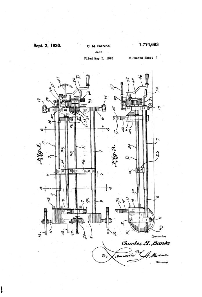
The jack is built on a “truck” frame (A) that is adjustable to accommodate vehicles with different wheelbases.
- Telescopic Side Members: The frame consists of tubular sections (7) and internal rod sections (8). This “sleeve” design allows the front and rear of the jack to slide toward or away from each other.
- Adjusting Rod (48): To change the length of the jack, the operator turns a crank handle (52). This rotates a threaded rod that feeds through a socket (50) on the front cross member, mechanically pushing or pulling the two halves of the frame to the desired length.
2. Simultaneous Dual-Lift Mechanism
The primary feature of the device is its ability to raise two separate lift heads (B and C) using a single operating point.
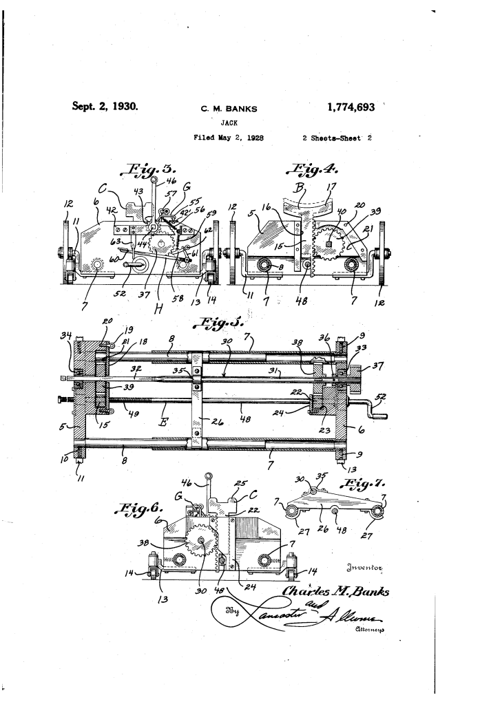
- Jack Shaft (30): A long shaft runs the length of the frame. It features a cylindrical portion (31) at the rear and a squared portion (32) at the front.
- Sliding Gears: Because the front lifting gear (39) has a square bore, it can slide along the squared shaft as the frame is extended or retracted, while still maintaining a mechanical connection to the shaft.
- Rack and Pinion: Both lifts use rack bars (15, 22). When the operator turns the main crank (46), the shaft rotates, and the gears drive both racks upward at the exact same time and speed.
3. Vertical Differential Adjustment
Banks recognized that the front and rear axles of a car are rarely at the same height. To solve this, he included a “manual override” for the front lift.
- Removable Cover Plate (18): By removing this plate, the operator can temporarily slide the front gear (39) out of alignment with the rack.
- Pre-setting Height: The operator can then manually raise or lower the front lift (B) to match the vehicle’s specific axle clearance. Once aligned, the gear is slid back into place, and the two lifts will operate in sync from that point forward.
4. Safety and “Step-by-Step” Lowering
To prevent the heavy vehicle from dropping suddenly, Banks engineered a dual-keeper system (G and H) that provides a ratcheting safety mechanism.
| Component | Function |
| Latch (55) | A spring-loaded arm that engages the teeth of the drive pinion. |
| Pawl (58) | A secondary safety catch that engages the larger drive gear. |
| Step-Movement | By alternately releasing the latch and the pawl, the operator can lower the vehicle “tooth by tooth.” This provides a slow, controlled descent that prevents mechanical shock or injury. |
Engineering Significance
Charles M. Banks’ 1930 patent represents a bridge between simple mechanical lifting and modern hydraulic shop lifts.
- Brake Calibration: By enabling the simultaneous elevation of all four wheels, Banks provided the necessary infrastructure for the safe implementation of four-wheel brakes.
- Mechanical Synchronization: The use of a squared shaft to allow gear travel while maintaining torque was a sophisticated solution to the “variable wheelbase” problem.
- Ergonomics: The entire operation—adjusting the length, lifting the car, and the controlled lowering—is performed from a standing position at one end of the jack.
