
Rail Brace (Ned E. Barnes, No. 1,446,957)
The patent by Ned E. Barnes of Willis, Texas, describes a Rail Brace (Patent No. 1,446,957, 1923). This invention is a heavy-duty mechanical fastener designed to secure railroad tracks to their ties and, most importantly, to prevent “spreading”—the dangerous outward shifting of rails caused by the weight and speed of passing trains. Barnes’s primary objective was to create a brace that was simple to manufacture, easy to install, and adjustable to accommodate the slight variations in track width required during rail laying.
Inventor Background: Ned E. Barnes
Ned E. Barnes was an African American inventor based in Montgomery County, Texas. His 1923 patent addresses one of the most persistent safety issues in early 20th-century railroading: track stability. During this era, as locomotives became heavier and faster, the lateral pressure exerted on rails (centrifugal force) often caused spikes to loosen. Barnes’s solution moved away from simple vertical spikes toward a horizontal clamping system that utilized the physics of the wedge.
Key Mechanical & Structural Systems
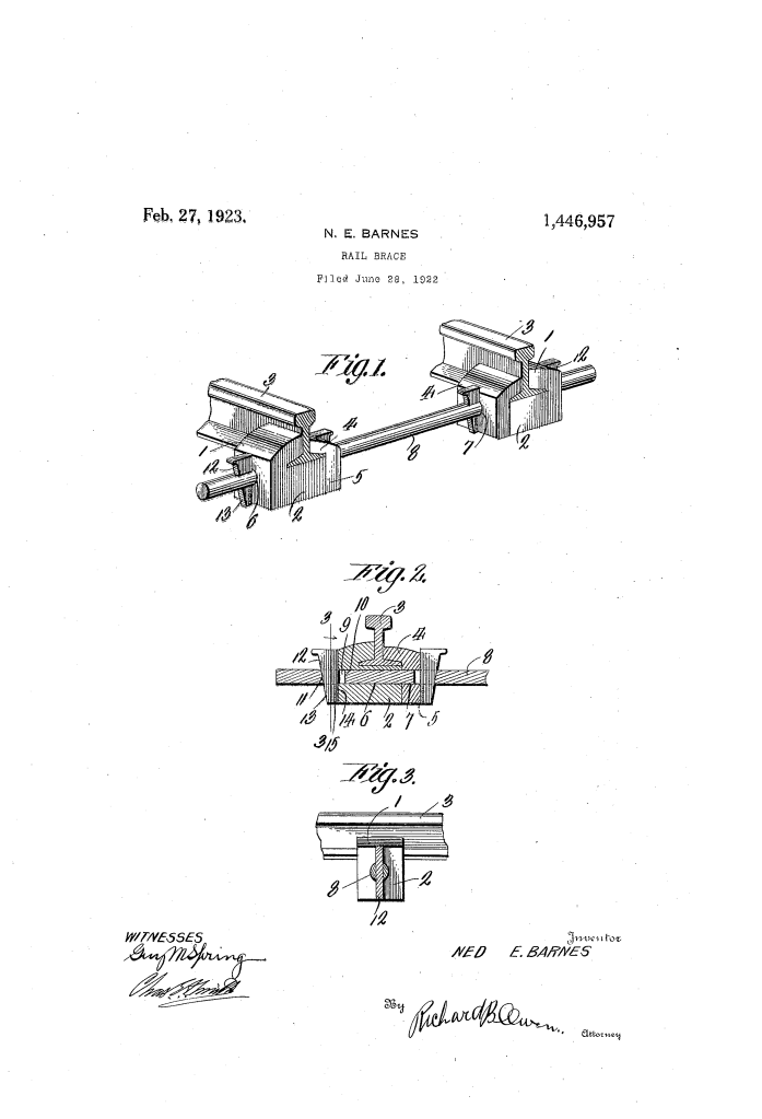
The system consists of two mirror-image braces connected by a central tie rod, creating a unified “grip” across the entire width of the track.
1. The Dual-Jaw Clamping Mechanism (1, 4)
- Outer Jaw (1): This jaw is integral to the base plate (2) on which the rail sits. It grips the outer edge of the rail foot.
- Inner Jaw (4): This is a separate component formed with a leg (5). It slides over the inner edge of the rail foot.
- Registration: When placed together, an opening (6) in the base plate aligns perfectly with an opening (7) in the leg of the inner jaw.
2. The Tie Rod (8)
- Function: A horizontal rod extends between the two rails of the track, passing through the aligned openings of the braces on both sides.
- Locking Slots (9): Near each end, the rod features precisely machined openings. These slots have one straight vertical side (10) and one slanting side (11).
3. The Adjustable Wedge System (12, 15)
- The Wedges (12): These are the primary “tighteners” of the system. Each wedge has a straight side and a slanting side to match the slots in the tie rod.
- Tensioning: As the wedges are driven down into the slots, they force the inner jaw (4) and the outer jaw (1) toward each other, creating an immense clamping force on the rail.
- Variable Spacing: By driving one wedge deeper than its counterpart, the rail can be shifted slightly along the rod. This allows track layers to fine-tune the “gauge” (the distance between rails) with extreme precision.
Engineering Features and Safety Logic
| Feature | Hazard Addressed | Barnes’s Engineering Solution |
| Horizontal Tie Rod (8) | Rail Spreading. | Physically links the two rails together so they cannot move independently. |
| Slanting Wedge (12) | Loose fasteners. | Uses mechanical advantage to create a “permanent” grip that tightens with friction. |
| Cotter Pins (15) | Vibration displacement. | Multiple apertures in the wedge allow it to be locked in place, preventing it from “jumping” out due to train vibrations. |
| Modular Design | Difficult repairs. | The system can be disassembled by simply removing the cotter pins and knocking out the wedges. |
Significance to Railway Engineering
Ned E. Barnes’s rail brace represents a sophisticated evolution in permanent way (track) engineering.
- Lateral Force Resistance: By using a tie rod that spans the distance between rails, Barnes converted lateral outward pressure into a “tension” force on the rod, which is much easier for steel to handle than the “shear” force applied to traditional wooden spikes.
- Adjustability: His design recognized that railway tracks are not static; they expand and contract with heat. The ability to shift the brace longitudinally along the rod provided a level of flexibility that rigid spikes lacked.
- Reliability: The use of “spaced openings” and “wedges” is a timeless engineering principle (the inclined plane) that provides maximum holding power with minimal moving parts.
