
Improvement in Screw-Presses (Peter R. Campbell, No. 213,371)
The patent by Peter R. Campbell of Hurricane, Mississippi, describes an Improvement in Screw-Presses (Patent No. 213,371, 1879). The object is to furnish an improved screw-press that can be operated by steam, horse-power, or other external power, while being simple in construction, easily adjusted and controlled, and reliable in operation.
Inventor Background: Peter R. Campbell
Peter R. Campbell was an inventor residing in Mississippi. His invention targets the large-scale agricultural sector of the late 19th century, where screw presses were essential for baling cotton, hay, or extracting oil from seeds. The focus on integrating external power (steam, horsepower) with simple, mechanical control mechanisms (clutches and shifting gears) reflects the era’s drive for mechanized efficiency in agriculture.
Invention and Mechanism
The press uses a multi-stage gear system with external levers for both engaging the power source (clutch) and reversing the direction of the press screw.
1. Power Engagement (Clutch)
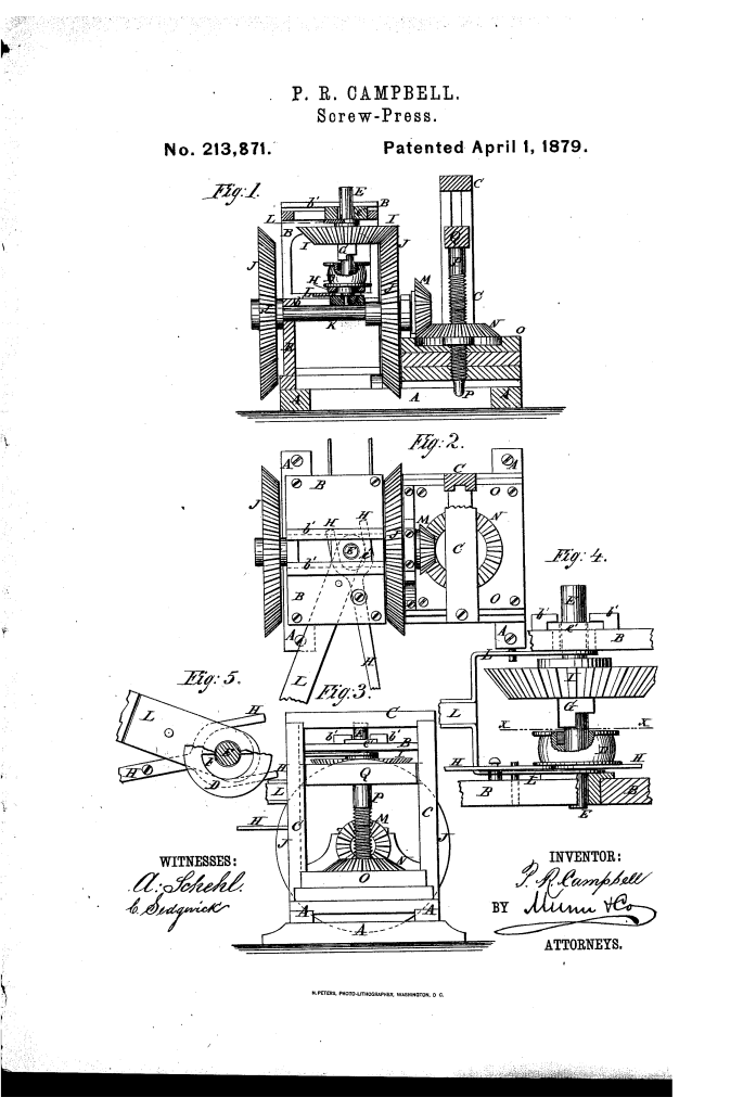
- Band-Wheel (D): The primary wheel, driven by a belt from the external power source, revolves loosely on the shaft (E).
- Clutch (F, G): The hub of the band-wheel has a recess (F) to engage a clutch-piece (G) attached to the shaft (E).
- Lever H: A lever whose inner end is forked to pass around the shaft (E) and is used to raise and lower the band-wheel (D) to throw the clutch into or out of gear.
- Function: This lever allows the operator to instantly engage or disengage the power to the press.
2. Direction Reversal (Shifting Gear) (Key Innovation)
- Shaft (E) and Gear (I): The shaft (E) has a large bevel-gear wheel (I) attached to it.
- Opposing Gears (J): Two bevel-gear wheels (J) are attached to a second shaft (K) on opposite sides of the frame.
- Lever L: A lever used to move the entire shaft (E) laterally.
- Function: Moving the shaft (E) causes the large gear (I) to mesh with either one or the other of the opposing gears (J). Since the gears (J) rotate the shaft (K) in opposite directions, this action instantly reverses the direction of the press screw (P) for pressing or releasing the bale.
3. Press Screw Drive
- Screw (P) and Follower (Q): The main press screw, attached to the cross-head or follower (Q).
- Socket-Held Wheel (N): A bevel-gear wheel (N) swiveled to the press frame. Its eye is threaded to fit upon the screw (P).
- Final Drive: The second shaft (K) drives a small bevel-gear wheel (M), which meshes with the threaded gear wheel (N), turning the screw (P) up or down.
Concepts Influenced by This Invention
Campbell’s screw-press influenced subsequent industrial and agricultural machinery by pioneering a highly effective integrated mechanical transmission for direction control and power engagement.
- Single-Shaft Direction Reversal (Shifting Gears): The most direct influence is the mechanism for instantaneous direction reversal by laterally shifting a single driving gear (I) to engage one of two opposing driven gears (J). This principle is a fundamental, robust method of reversing direction used in early lathes, winches, and mechanized screw drives .
- Controllable Power Engagement (Clutch): The use of a clutch (F, G) operated by a simple external lever (H) to isolate the press from the continuous external power source influenced the design of all subsequent industrial machines, providing necessary safety and stop control.
- Screw Press Actuation: The entire geared system, designed to efficiently deliver high torque to a central screw for compression, is foundational to the design of heavy-duty mechanical presses and industrial balers .
- Combined Control Levers: The use of two separate, non-interfering levers (H for power ON/OFF, L for direction UP/DOWN) for total machine control influenced the design of early industrial control interfaces.
