
Improvement in Rotary Engines (Benjamin H. Taylor, No. 202,888)
The patent by Benjamin H. Taylor of Rosedale, Mississippi, describes an Improvement in Rotary Engines (Patent No. 202,888, 1878). The invention focuses on the specific construction and arrangement of the wheel, casing, and abutments to create a functional and reversible rotary steam engine.
Invention and Mechanism
The engine converts steam pressure directly into rotational motion using a central wheel with spring-loaded, sealed vanes.
1. Rotary Wheel and Sealing
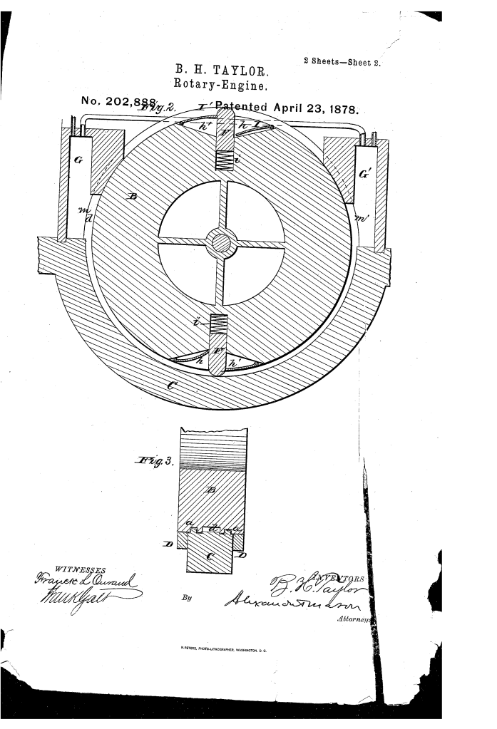
- Central Shaft (A) and Wheel (B): The central rotating component (the rotor), preferably made in a skeleton form.
- Casing (C): A fixed casing or rim surrounding the lower half of the wheel (B).
- Sealing Grooves: The wheel’s periphery has two circumferential grooves (
), into which fit two longitudinal rims or flanges (
) on the fixed casing (C).
- Function: This arrangement forms a steam-tight joint between the wheel and the casing.
- Steam Channel (): A central circumferential groove (
) is made in the periphery of the wheel (B) between the sealing grooves (
), forming the working channel for the steam.
2. Spring-Abutments and Pockets (The Vanes)
- Transverse Abutments (F, F): Two or more vanes (or abutments) are placed in radial grooves in the wheel.
- Spring Force: They are forced outward against the casing by spiral springs () placed behind them.
- Function: The spring pressure ensures the abutments maintain a tight seal against the inner surface of the casing (C) as they rotate.
- Pockets () and Valves (I, I): On the sides of each abutment (F) are recesses or pockets () covered by hinged valves or plates (I, I).
- Function (Power Generation): The pockets increase the surface area on the abutment against which the steam works, increasing efficiency. The valves (I) are arranged to cause the steam to act on one side only.
3. Steam Flow and Reversibility
- Steam Chests (G, ): A steam chest is located at each end of the casing (C), communicating with the central steam channel (
).
- Piping and Stop-Cocks: Connected inlet pipes (H, H) and exhaust pipes (
) are provided. Stop-cocks control the flow to either chest.
- Reversibility: The engine is reversed by:
- Reversing the valves (I, I) in the pockets (
) (i.e., opening one pocket and closing the other).
- Reversing the stop-cocks in the inlet and exhaust pipes. Steam is then admitted to the opposite chest (
), reversing the direction of the wheel.
- Reversing the valves (I, I) in the pockets (
Historical Significance and the Inventor
Benjamin H. Taylor’s 1878 patent is part of the extensive 19th-century effort to develop a successful Rotary Engine.
- The Rotary Engine Problem: Inventors were driven by the desire to create an engine that converts steam power directly into rotation, eliminating the need for a piston’s linear motion, connecting rods, and cranks (like in conventional reciprocating steam engines). This promised a simpler, more compact, and potentially more efficient design.
- Vane Sealing: Taylor’s design is typical of vane-type rotary engines. The core engineering challenge was maintaining a steam-tight seal between the rotating vanes (abutments F) and the fixed casing (C). Taylor’s use of springs () to continuously push the vanes outward and the flange-and-groove system () for the wheel itself was his contribution to solving the sealing problem.
- The Inventor (Benjamin H. Taylor): Taylor, residing in Rosedale, Mississippi, was one of many inventors working to advance steam technology in the post-Civil War industrial landscape.
Concepts Influenced by This Invention
Taylor’s engine utilized principles essential to modern fluid and power machinery, particularly those dealing with rotational sealing and positive displacement.
- Sliding Vane Rotors: The fundamental mechanism of a rotor with radial vanes/abutments that slide in and out against a fixed casing is the core design for modern sliding-vane compressors, vacuum pumps, and positive-displacement fluid pumps .
- Spring-Loaded Sealing: The concept of using spring pressure to continuously force a seal (like the abutments F) outward against a rotating or sliding surface is a standard engineering solution for maintaining fluid-tightness under dynamic conditions, used in modern rotary seals, packings, and centrifugal clutches.
- Flow Reversibility: The design where the direction of rotation is changed by simply reversing the inlet/exhaust ports and valve position is a standard feature in many modern industrial pumps and motors.
- Geometric Cavity Utilization: The use of pockets () with valves (I) to maximize the surface area exposed to steam pressure influenced the design of modern turbine blades and rotor vanes that use complex contours to efficiently capture and convert fluid energy.
