
The Hydromechanical Rate Damped Servo System (U.S. Patent 3,101,650), patented by John W. Blanton in 1963, represents a significant leap in control theory—specifically, the creation of a mechanical “lead” constant to manage systems with large dynamic time lags, such as gas turbines or jet engines.
The Problem: Mechanical Lag
In complex engines, there is often a significant delay between a control signal (like “increase speed”) and the actual mechanical response (the turbine spinning up).
- The Oscillation Risk: If a standard servo is used, it might apply too much power for too long, causing the engine to overspeed, then over-correct, leading to unstable hunting or “chugging.”
- The Traditional Fix: Engineers usually used complex electronic amplifiers and passive electrical networks to create “rate anticipation” (calculating the speed of the error change) to dampen the movement. Blanton’s goal was to do this entirely with hydraulics and mechanics, increasing reliability in harsh engine environments.
Core Innovation: The Load-Sensing Feedback Piston
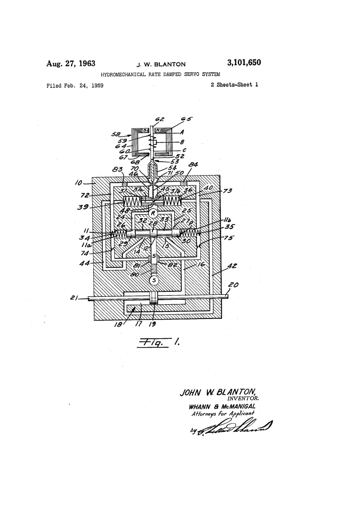
The heart of the system is the feedback piston (37), which serves as a mechanical differentiator. It measures the velocity of the actuator and feeds that information back to the control valve to “dampen” the action before the engine overshoots its target.
1. The Orifice-Piston Mechanism
The feedback piston is housed in a bore (36) and features a calibrated restricted orifice (37b) running through its center.
- Velocity Sensing: As the actuator (18) moves, it forces fluid into the feedback bore. This fluid must pass through the orifice.
- Pressure Drop: The flow through the orifice creates a pressure differential proportional to the velocity of the actuator.
- Spring Displacement: This pressure drop moves the piston against its centering springs (39, 40). Therefore, the physical position of the piston at any moment is a direct representation of how fast the actuator is moving.
2. The Feedback Loop
The piston is connected to a feedback spring (50), which is attached to the flapper valve (53).
- Negative Feedback: When the torque motor (58) tells the system to move, the feedback piston moves in the opposite direction.
- The “Washout” Effect: Because of the orifice, the piston eventually centers itself once the actuator stops moving or reaches a steady state. This “washes out” the signal, ensuring that the damping only happens while the system is accelerating or decelerating.
System Components and Flow
| Component | Function |
| Torque Motor (58) | Converts electrical input signals into a mechanical pivot of the flapper stem (52). |
| Flapper Valve (53) | Controls the pressure in chambers 11a and 11b by partially blocking nozzles 70 and 71. |
| Power Valve (P) | The main “spool” that directs high-pressure fluid to the actuator cylinder (17). |
| Actuator (18) | The heavy-duty piston that physically moves the engine components (e.g., fuel valves or vanes). |
Operation: Achieving “Lead Time”
When a sudden “increase speed” signal is received:
- Initial Kick: The power valve (P) opens wide, sending a massive hydraulic force to the actuator to overcome static friction and inertia.
- Anticipation: As the actuator begins to accelerate rapidly, the feedback piston (37) deflects.
- Early Throttling: This deflection tugs on the flapper valve, partially closing the power valve before the target speed is reached.
- Stability: This prevents the actuator from “slamming” into position or overshooting, allowing it to settle at the design velocity with high precision and no oscillation.
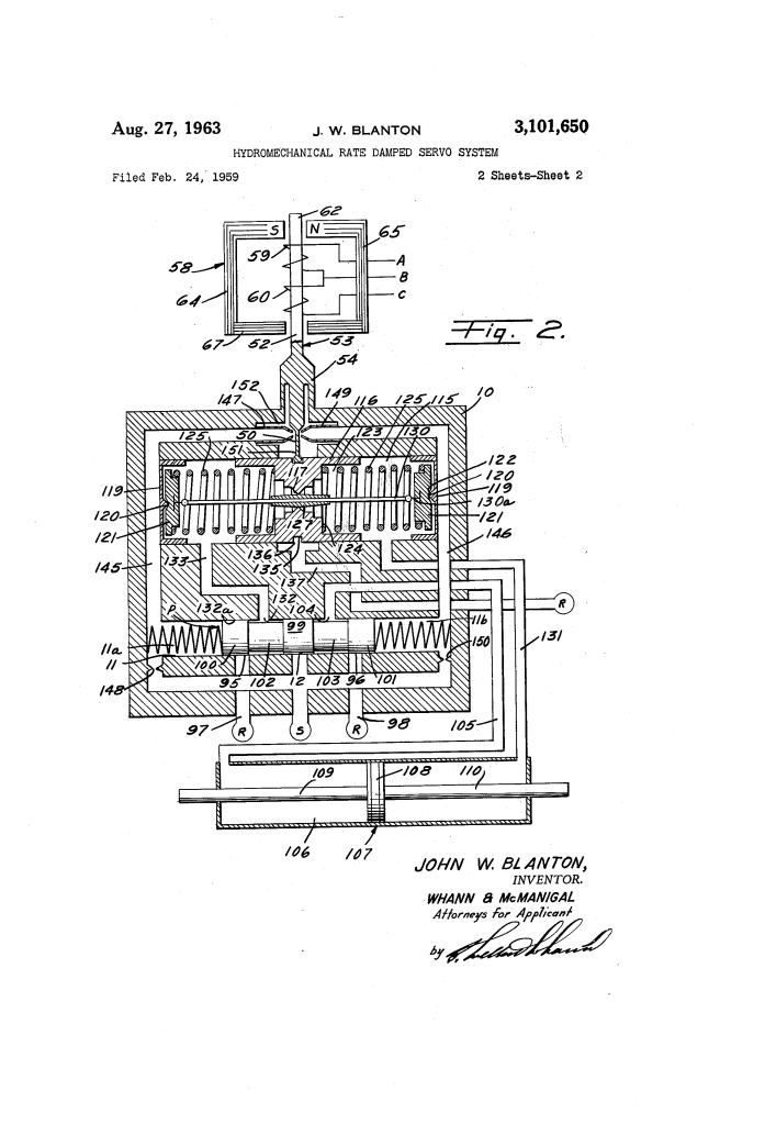
Variable Orifice Modification (Figure 2)
In a more advanced version (Fig. 2), Blanton introduced a tapered control member (127) inside the feedback piston’s orifice (117).
- Linearity: As the piston moves further, the orifice size changes. This allows for even more precise control over the damping rate, ensuring the response is linear regardless of how large the initial error signal was.
Significance
This invention allowed for high-performance jet engine controls that were purely hydromechanical. It eliminated the need for fragile vacuum tubes or early transistors in high-heat areas, providing “lead/lag” compensation through the clever use of fluid dynamics and spring rates.
