
Hydraulic Shock Absorber (1968)
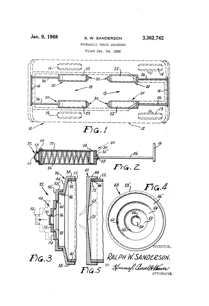
U.S. Patent No. 3,362,742, granted on January 9, 1968, to Ralph W. Sanderson, describes a variable-aperture hydraulic shock absorber engineered to dissipate vehicle collision forces. Sanderson, an inventor based in Washington, D.C., developed this device to mitigate structural vehicle damage and reduce the severity of injuries sustained by occupants during automobile crashes.
This invention addressed an operational dilemma in vehicle collision safety: early hydraulic bumpers were tuned to a single pressure threshold. If calibrated for low-speed impacts, the mechanism would bottom out during a severe crash, failing to absorb high-energy shock waves. Conversely, if built to withstand heavy collisions, the system remained rigid during minor impacts, transmitting the full deceleration jolt directly to the passengers. Sanderson solved this by introducing an end closure that selectively creates larger discharge apertures as impact severity increases.
The Core Design: Selective Blowout Apertures
The assembly connects a vehicle bumper to the chassis using a cylinder filled with an incompressible fluid (such as hydraulic fluid or water) and a spring-loaded piston. The breakthrough lies in the cylinder’s relief cap, which provides a staged discharge opening that expands in direct proportion to the collision’s magnitude.
Sanderson detailed two distinct configurations for achieving this adaptive behavior:
- Concentric Blowout Plugs (Figures 3 and 4)
- The cylinder cap houses a series of concentric, nested segments: a central circular plug (50) set inside an intermediate annular plug (52), which rests inside a outer annular plug (54).
- The holding force between nested rings is calibrated via mechanical interference (friction fits, shrink fits) or controlled adhesive bonds.
- A low-speed impact drives the piston backward, producing a moderate pressure pulse that expels only the center plug (50), creating a small discharge orifice (56).
- A high-speed crash generates a powerful, rearward-traveling hydraulic shock wave that overcomes the retention forces of the larger outer rings, dislodging intermediate plug 52 or outer plug 54 (often shearing the entire nested stack intact) to open a much wider fluid exhaust port (58 or 60).
- Contoured Diaphragm Cap (Figure 5)
- In this unitary embodiment, the closure cap (62) features a solid metal wall (68) that varies continuously in thickness from a thin, easily ruptured center (70) to a thick, reinforced outer perimeter (72).
- Upon impact, internal hydraulic pressure fractures the weakest central section first.
- As collision energy mounts, the tear propagates radially outward into the thicker material, dynamically creating an aperture sized to match the force of the collision.
How the Apparatus Functions
The device operates through a sequenced transfer of kinetic energy into hydraulic flow:
| Step | Action | Safety Purpose |
| 1. Impact Transfer | Bumper 16 strikes an object, forcing piston rod 26 and piston 24 rearward into housing 22. | Translates external crash velocity into internal linear piston travel. |
| 2. Spring Compression | Helical spring 34 compresses against piston 24. | Provides initial mechanical resistance and immediate energy absorption. |
| 3. Shock Wave Propagation | Fluid displacement generates a steep, rearward-traveling pressure pulse through the captive liquid. | Directs concentrated hydraulic force toward the rear relief closure. |
| 4. Selective Blowout | Pressure dislodges central plug 50, annular rings 52 or 54, or tears contoured diaphragm 68. | Opens a discharge orifice sized to match crash severity, venting fluid to cushion the impact. |
Technical Components
- Cylinder Housing (22): High-strength metal tube containing the incompressible hydraulic fluid or water, sealed at the front by closed wall 30 and O-ring 32.
- Piston Assembly (24, 26): Slidable piston head driven by an operating rod rigidly affixed to the vehicle bumper (16).
- Internal Biasing Spring (34): Helical spring that returns the piston to its starting position and absorbs initial low-speed collision energy.
- Adapter Collar (36): Heavy-duty threaded connector linking the main cylinder wall (38) to the relief cap assembly via conical transition wall 44.
- Multi-Stage Relief Cap (48, 56′): Concentric retaining plate supporting nested blowout plugs (50, 52, 54) to create graduated fluid outlets (56, 58, 60).
- Tapered Rupture Cap (62): Unitary alternative closure featuring a variable-thickness wall (68) that fractures progressively from core (70) to perimeter (72).
Automotive Safety and Engineering Impact
Sanderson’s hydraulic architecture addressed core occupant-deceleration challenges during the transition toward modern automotive crash structures:
- Dynamic Energy Regulation: Rather than relying on a static shear pin, the multi-stage blowout geometry matched fluid throttling resistance to kinetic impact energy.
- Anti-Bottoming Protection: Opening progressively larger exhaust areas prevented hydraulic lock, eliminating catastrophic passenger compartment deceleration spikes.
- Dual Mechanical Damping: Combining a coil spring with high-velocity liquid extrusion provided an early precursor to the energy-absorbing bumper systems mandated on passenger vehicles in the 1970s.
About the Inventor: Ralph W. Sanderson
Ralph W. Sanderson was an inventor based in Washington, D.C. Working in the mid-1960s, Sanderson developed practical mechanical and fluid-power solutions aimed at automotive crash survivability, focusing on mitigating collision trauma through kinetic energy dispersion and progressive hydraulic release mechanisms.
Summary of Claims
The patent explicitly claims:
- A vehicle collision force dissipator comprising a cylinder with a bumper-connected piston, an internal liquid chamber, and an end closure adapted to separate sequentially into a plurality of components.
- An end closure combining a frictionally fitted outer annular member and an inner plug member designed to detach at different impact pressures.
- A multi-stage concentric plug assembly where successive annular rings separate sequentially under progressively increasing hydraulic forces.
- An alternative unitary cap of variable cross-section, featuring a thin central zone that ruptures under lower impact pressures and a thicker peripheral zone that tears open only under higher collision loads.
