
Hydraulic Jack (Charles M. Banks, No. 1,753,640)
The patent by Charles M. Banks of Chicago, Illinois, describes an improved Hydraulic Jack (Patent No. 1,753,640, 1930). This invention provides a more durable, efficient, and user-friendly tool for lifting heavy loads, such as automobiles. Banks’ design focuses on a specialized release valve system and a simplified pumping mechanism that could be operated entirely with a single, multi-purpose handle.
1. Core Components and Layout
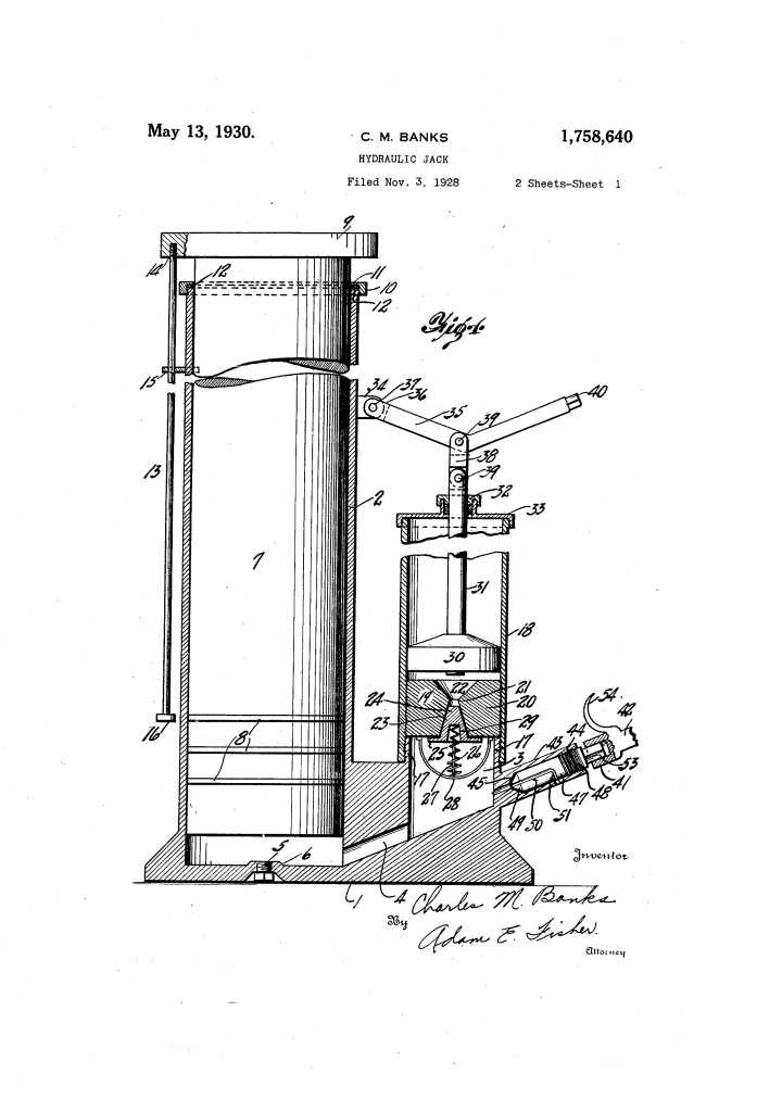
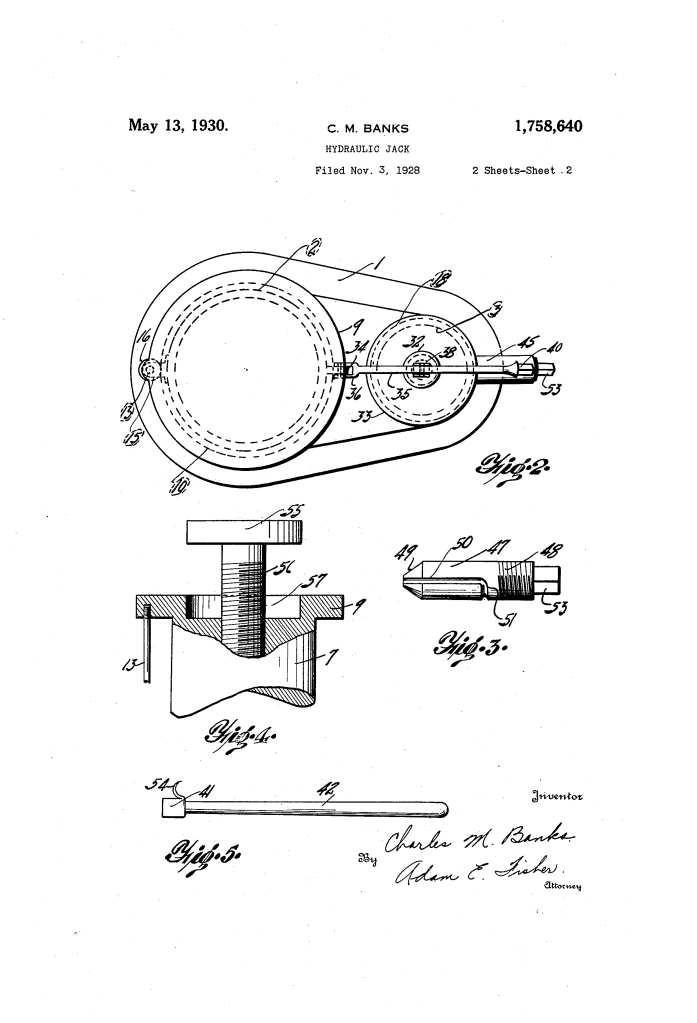
The jack is built upon an elongated base (1) that houses two vertical cylinders connected by an internal passage.
- Jack Cylinder (2): The larger cylinder contains the Ram or Plunger (7). This is the component that actually lifts the load.
- Pump Cylinder (18): A smaller cylinder where the operator creates pressure. It is connected to the jack cylinder via an angular port (4).
- Work Engaging Head (9): A wide circular head at the top of the plunger to provide a stable contact point for the load.
- Guide and Stop Rod (13): A safety feature that prevents the plunger from rotating and limits its upward travel so it cannot be accidentally pumped out of the cylinder.
2. The Pumping and Valve Mechanism
The efficiency of Banks’ jack lies in its Inlet Valve (19) and Compression Piston (30).
- Pumping Action: The operator uses a lever (35) to reciprocate the piston (30). On the downstroke, fluid (oil) is forced through the inlet valve.
- Spring-Loaded Inlet Valve: The valve (24) is held in its seat by a coil spring (26). It is designed to “seat upwardly,” meaning it opens when the pump pressure exceeds the spring tension and the internal pressure of the base.
- Modulation: This valve ensures a “steady and even” rise of the ram, preventing the jerky movements common in lower-quality jacks.
3. The Specialized Release Valve (47)
One of the most innovative aspects of the Banks patent is the Release Valve, which allows the user to lower the load safely and precisely.
- Grooved Design: The cylindrical valve (47) features a longitudinal groove (50) that turns circumferentially.
- Operation: To lower the jack, the user turns the valve. When the groove aligns with an escape aperture (52), the internal pressure is vented, allowing the plunger to descend.
- Positive Seating: When closed, the tapered end (49) of the valve seats firmly, ensuring a leak-proof seal while the jack is under load.
4. The Multi-Purpose Operating Handle (42)
Banks engineered the jack to be operated by a single tool, enhancing convenience in cramped spaces.
| Feature | Function |
| Socket End (41) | Fits onto the squared end (40) of the pump lever to raise the jack. |
| Release Fitting | Fits onto the squared end (53) of the release valve to lower the jack. |
| Arcuate Hook (54) | Used to hook onto the jack and pull it out from under a vehicle without the user having to reach underneath. |
5. Auxiliary Extensible Head (Fig. 4)
Banks also included a modification for the Plunger Head (9).
- Threaded Shank (56): An auxiliary head (55) can be screwed up or down.
- Precision Adjustment: This allows the user to bridge the gap between the jack and the work surface before pumping begins, ensuring the jack’s full stroke is used for lifting rather than just “taking up the slack.”
Significance to Automotive Engineering
Charles M. Banks’ 1930 patent represents a period of refinement in hydraulic tools. By integrating safety stops, a precisely controlled release mechanism, and a “hands-off” retrieval hook, he addressed the primary safety concerns of early 20th-century mechanics. The design minimized the risk of sudden load drops and simplified the mechanical interface, making the hydraulic jack a standard piece of equipment for both professional garages and individual car owners.
