
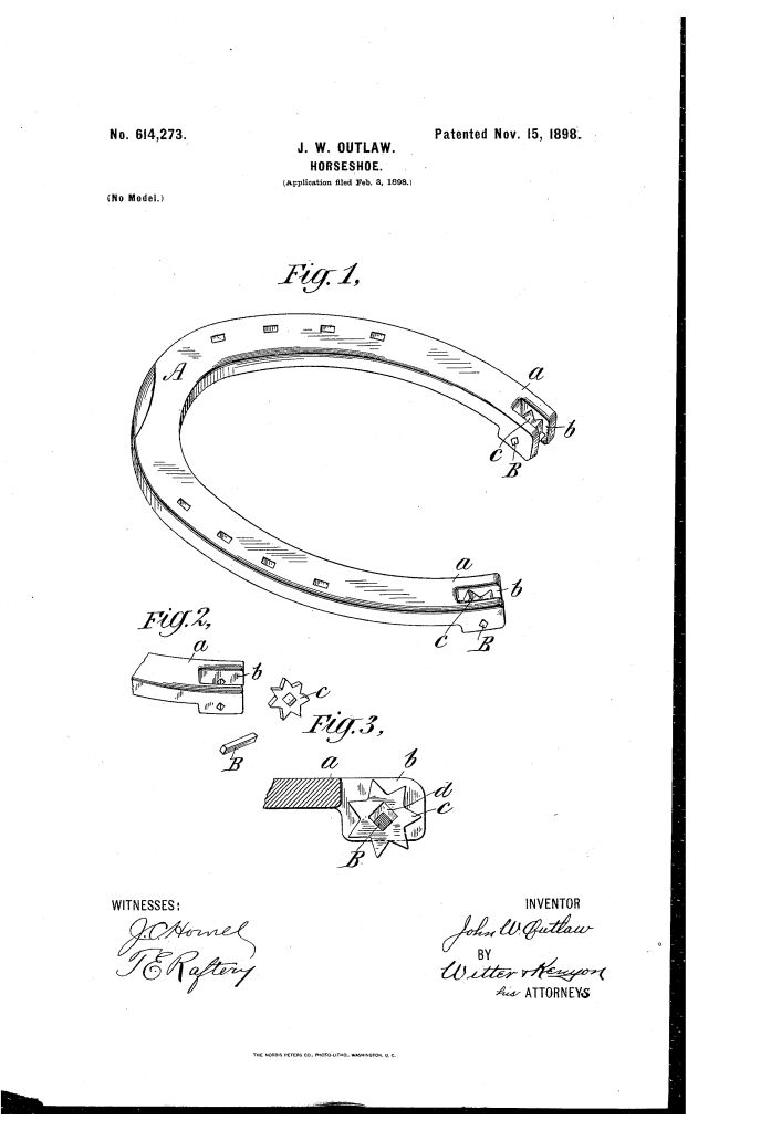
Self-Sharpening Anti-Slip Horseshoe (1898)
U.S. Patent No. 614,273, granted on November 15, 1898, to John W. Outlaw, introduces a mechanical traction system designed to secure a reliable foothold for horses on smooth or slippery urban pavements. Based in New York City, Outlaw engineered a solution to an urgent urban transit hazard: working horses slipping and injuring themselves on slick cobblestones, asphalt, and frozen streets.
Standard horseshoes of the late 19th century relied on static calks (projections on the heel or toe) that rapidly wore down, went dull, or required frequent trips to a blacksmith for replacement. Outlaw bypassed this limitation by building a dynamic, self-indexing traction mechanism directly into the heel of the shoe.
The Innovation: The “Polygonal Locking Roller”
The core breakthrough of Outlaw’s design is a hardened steel toothed roller that freely rotates when the horse lifts its hoof, but automatically locks into a rigid, non-slip calk the instant the horse’s weight contacts the ground.
- The Thickened Heel and Slot (a, b)The shoe body (A) is forged with heels (a) made thicker than standard shoes. Each heel contains a vertical longitudinal slot (b) that houses a hardened steel roller (c) equipped with pointed teeth (preferably seven).
- The Polygonal Axle and Bore (B, d)Rather than using a smooth circular axle—which would spin under load and cause the animal to slip—Outlaw used a polygonal axle passing through a matching polygonal hole (d) in the roller. In the preferred embodiment, both the axle and the hole are square:
- Clear Clearance: The hole is dimensioned slightly larger than the axle so the roller rotates freely when free of downward load.
- Diagonal Alignment: The square axle is oriented so its diagonals sit perpendicular and parallel to the plane of the shoe (B).
How the Mechanism Operates
The assembly cycles automatically through four phases with every stride:
| Step | Mechanical Action | Traction Purpose |
| 1. Ground Contact | As the hoof lands, the horse’s weight forces the roller upward inside slot b. | Engages the locking mechanism against the axle. |
| 2. Self-Centering Lock | The oversized square hole d is forced into alignment over the diagonal points of the square axle. | Prevents rotation; unstable equilibrium forces the roller to remain rigidly locked under load. |
| 3. Surface Bite | The lowest tooth projects below the thickened heel into the pavement surface. | Provides an immoveable, biting foothold against ice, mud, or slick stone. |
| 4. Free Indexing | When the horse lifts its hoof, gravity and ground release drop the roller away from the axle. | The roller is free to revolve, presenting a fresh, sharp tooth for the next stride. |
Key Mechanical Components
- Shoe Body (A): A forged horseshoe frame featuring reinforced, extra-thick heel sections (a) to enclose and protect the inner mechanism.
- Vertical Slot (b): A protective housing carved into each heel that accommodates the roller while limiting horizontal drift.
- Toothed Roller (c): A hardened steel wheel, preferably featuring seven biting points, designed to withstand continuous impact against hard city streets.
- Polygonal Bore (d): An internal square aperture that creates an automatic mechanical stop against the axle when forced upward.
- Geometric Axle (B): A square steel pin fixed transversely through the slot walls, positioned at an angle to arrest rotation under vertical pressure.
Urban Transit and Practical Impact
In the late 19th century, draft animals formed the absolute backbone of municipal shipping and passenger transport. Smooth asphalt paving and winter conditions frequently brought city commerce to an abrupt standstill:
- Continuous Self-Renewal: Because the wheel freely revolves between steps, wear distributes evenly across all points, dramatically extending the lifespan of the shoe compared to stationary heel calks.
- Hoof Protection: The patent notes that the upper slot can be enclosed, shielding the horse’s hoof from the top teeth while allowing the bottom tooth to bite cleanly into the road.
- Versatile Placement: Outlaw noted that the self-locking rollers could be installed at both the toe and heels depending on the pulling needs of the team.
About the Inventor: John W. Outlaw
John W. Outlaw was an inventor active in New York City during the late 19th century. Designing solutions at the height of the Gilded Age’s urban transit boom, Outlaw focused on practical mechanical interventions for urban infrastructure. Assigning a one-fourth interest to Gelinda Porter Robinson, his 1898 patent demonstrates a sophisticated grasp of applied geometry, solving a major transportation problem without relying on complex springs or manual adjustments.
Summary of Claims
The patent explicitly claims:
- The combination of a horseshoe and a toothed roller adapted to revolve when relieved from pressure, governed by a polygonal axle and larger matching hole.
- The specific configuration of a square hole turning on a fixed square axle mounted in the heel slot.
- Orienting the square axle such that its diagonals align parallel and perpendicular to the plane of the shoe, locking the wheel in place solely through the application of weight.
