
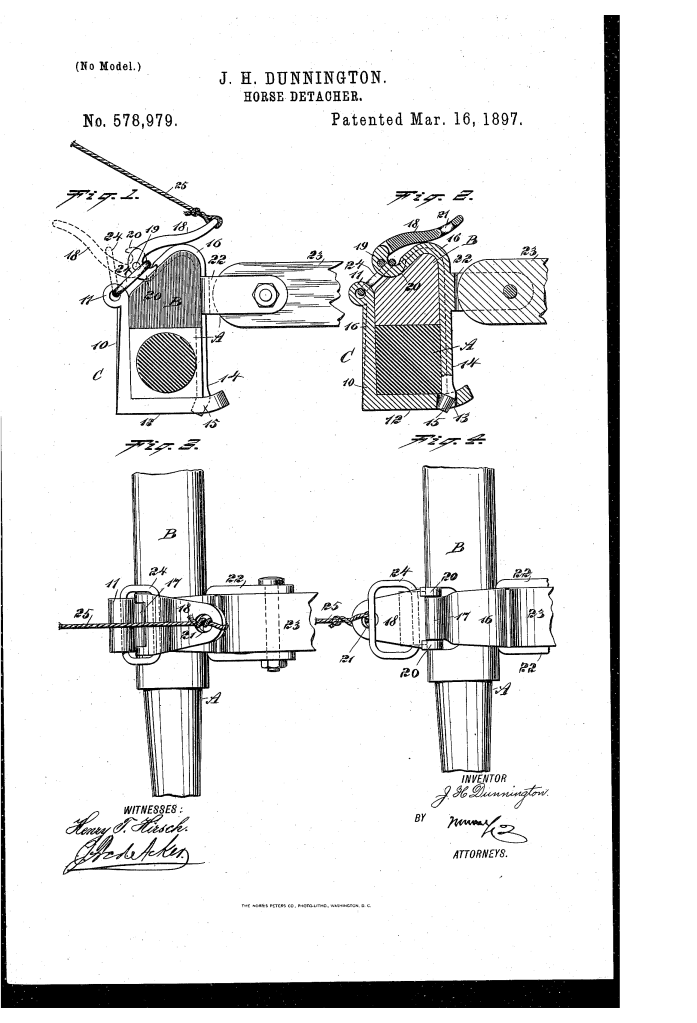
Horse-Detacher (1897)
U.S. Patent No. 578,979, granted on March 16, 1897, to James H. Dunnington, addresses a major safety hazard of nineteenth-century horse-drawn transit: runaway or unruly horses.
When a horse bolted, carriage passengers faced catastrophic collisions or overturning carriages, with no quick way to separate the animal from the vehicle. Dunnington, an inventor from Washington, Pennsylvania, engineered an emergency release mechanism directly integrated into the vehicle’s front axle assembly. It allowed vehicle occupants to instantly and cleanly detach the carriage thills (shafts) from inside the cab while in motion.
The Core Design: The Two-Part Quick-Release Clip
The foundation of Dunnington’s invention is a separable two-piece clip (C) that fits around the front axle (A) and axle-bed (B). Under normal driving conditions, it behaves with the rigid strength of a standard axle clip, but disengages immediately when triggered.
1. The Rear Body-Section (10, 12)
- An angular member fitted into a vertical channel along the back of the axle and axle-bed.
- The upper end terminates in an eye (11) that holds a freely movable connecting link (24).
- The horizontal lower member (12) extends beneath the axle toward the front, terminating in an upturned end with a dedicated locking opening (13).
2. The Front Thill-Carrying Section (14)
- A contoured vertical member fitted to the front of the axle with a curved upper portion (16) conforming to the top of the axle-bed.
- The lower end forms a downward-tapered head (15) designed to seat loosely inside the opening (13) of the lower body-section.
- The front face features integrated ears or lugs (22) to which the carriage thill (23) is securely pivoted.
- The top end terminates in an eye (17) that serves as the fulcrum for an over-center lock-lever (18).
How the Mechanism Operates
The assembly utilizes a cam-locking principle to maintain structural rigidity during standard operation, balanced with rapid disengagement in an emergency.
| Step | Action | Mechanical Purpose |
| 1. Locking & Engagement | The lower head (15) is set into opening (13). The lock-lever (18) is passed through the link (24) and pressed forward/downward. | Dual forward hooks (20) draw the link over-center past the pivot pin (19), firmly clamping both sections around the axle. |
| 2. Normal Transit | The lever remains seated forward over the axle assembly. | Matches the holding strength of a standard solid axle clip during typical road stress. |
| 3. Emergency Trigger | The occupant pulls a cord or chain (25) attached to opening (21) at the free end of the lock-lever. | Draws the lever upward and rearward, shifting the cam hooks (20) out of engagement with the link (24). |
| 4. Instant Detachment | The pull of the runaway horse extracts the thill-carrying section (14) forward from the axle. | The horse runs clear with the shafts attached; the loose rear body-section (10) drops to the ground, bringing the vehicle safely to rest. |
Technical Components
- Axle & Axle-Bed (A, B): Formed with matching channels to seat the clip members flush against the running gear.
- Lock-Lever (18): Features a bifurcated pivoting base with curved cam hooks (20) that straddle eye (17) via pivot pin (19).
- Connecting Link (24): Loosely mounted in eye (11) on the rear section, serving as the bridge tensioned by the lock-lever.
- Operating Line (25): Flexible cord or chain extending from opening (21) directly to the passenger compartment for immediate access.
Historical Impact and Safety Significance
Dunnington’s quick-release system represented an important step forward in late-Victorian vehicle safety engineering:
- In-Cab Passenger Control: Unlike earlier disengaging devices that required the driver to reach down to the axle or step out of the vehicle, this design operated via an accessible line directly from the carriage seat.
- Fail-Safe Separation: By relying on gravity and forward draw to eject the front clip section (14) while dropping the rear section (10), the mechanism avoided mechanical jamming during high-stress runaway events.
- Mechanical Simplicity: It required no complex gearing or secondary locks, making it economical to produce, easy to install, and durable against dirt and road vibration.
About the Inventor: James H. Dunnington
James Henry Dunnington was an inventor based in Washington, Pennsylvania. His work in the late 1890s centered on practical mechanical improvements for horse-drawn utility vehicles and carriages, focusing on mechanical reliability, public safety, and ease of manufacturing during the peak of the carriage era.
Summary of Claims
The patent explicitly claims:
- A two-section horse-detaching clip comprising a rear axle-bed member and a front thill-carrying member.
- A loose interlock at the base where a tapered head (15) engages a lower horizontal aperture (13).
- An over-center lock-lever (18) featuring integrated cam hooks (20) mounted to the thill section.
- A connecting link (24) supported by the opposing body-section to receive and be locked by the cam lever.
