

Home Security System Utilizing Television Surveillance (1969)
U.S. Patent No. 3,482,037, granted on December 2, 1969, to Marie Van Brittan Brown and Albert L. Brown, describes a closed-circuit audiovisual surveillance and remote access system for residential protection. Marie Van Brittan Brown, a nurse living in Jamaica, Queens, New York, conceived the system alongside her husband Albert, an electronics technician, to address slow police response times and provide direct home security under the resident’s immediate control.
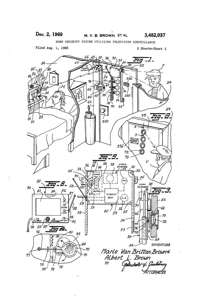
This invention solved a critical personal safety challenge: allowing an occupant inside a home or apartment to identify, interrogate, and admit or deter visitors outside the entrance door from a remote location—such as a bedroom—without ever opening the door or placing themselves in danger.
The Innovation: The Multi-Peephole Scanning and Remote Control System
Prior entrance monitoring relied on fixed optical peepholes, separate doorbells, or standard mechanical locks, all of which required the resident to walk up to the door and place themselves in proximity to an intruder.
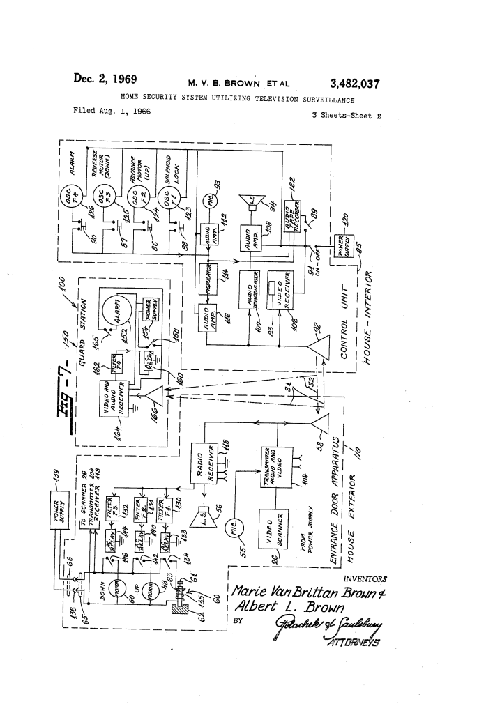
The Browns resolved this vulnerability by developing an automated door apparatus integrated wirelessly with a remote interior command console and an external central guard station.
Why the Motorized Scanner and Remote Interface?
- Height-Adjustable Perspective: A motorized internal carriage moves up and down behind a vertical column of peep windows, allowing residents to view visitors regardless of height (from small children to tall adults) or scan the ground for lurking prowlers.
- Spring-Loaded Lens Protection: Each optical peep hole is sealed with an automatic, spring-biased privacy flap that deflects out of the way only when the camera lens barrel passes it, preventing outsiders from peering in.
- Complete Remote Agency: From a bedside unit, an occupant can visually survey, converse bidirectionally, record visitor statements, unlock the door, or trigger an emergency distress call to emergency responders.
Key Mechanical and Electrical Components
The system operates as an integrated network of electromechanical and radio-frequency subsystems:
| Component | Function |
| Movable Door Cabinet (20) | A housing mounted to the rear of the entrance door (22) that travels vertically along a guide rail (34) and stationary gear rack (39). |
| Television Scanner (26) | A video camera with a forward-projecting lens barrel (28) configured to scan through vertically spaced optical apertures. |
| Elevation Drive (48, 50, 46, 42) | Dual electric motors powering a vertical worm drive and spur gear to raise and lower cabinet 20 along the gear rack. |
| Peep Apertures & Spring Flaps (68, 72, 74, 76) | A vertical array of lens-fitted holes in the door, each sealed by a pivoted metal flap returned to place by wire springs (76). |
| Solenoid Bolt Lock (60, 63, 135) | A radio-released deadbolt on the door frame that automatically retracts when energized by a remote command signal. |
| Interlock Safety Switch (65, 66) | A mating plug and receptacle across the door jamb that automatically cuts all electrical power to the door apparatus when the door is opened. |
| Remote Bedside Console (85) | An interior master station equipped with a video monitor (83), intercom speakers, push-button command oscillators, and an audio tape recorder (122). |
| Central Guard Station (150) | A remote monitoring facility equipped with an alarm (152), audio/video receiver (164), and frequency filter (162) to intercept emergency feeds. |
How the Apparatus Functions
The surveillance and security workflow proceeds through sequential stages dictated by the resident:
| Step | Action | Safety Purpose |
| 1. Visitor Arrival | A visitor approaches door 22; power interlock (65, 66) supplies current to scanner 26 and transmitter 104. | Instantly activates video broadcast to the remote bedside monitor without the occupant approaching the door. |
| 2. Height Adjustment | Resident depresses control buttons 86 or 87 on bedside console 85. | Motors 48 and 50 drive cabinet 20 up or down along rack 39, pushing aside flap 74 to align with the visitor’s face. |
| 3. Two-Way Interrogation | Occupant speaks into microphone 93; audio transmits via modulated RF carrier (S2) to door loudspeaker 56 via sound passage 225. | Allows safe verbal screening of visitors while receiving replies through door microphone 55. |
| 4. Audio Documentation | If an unwanted intruder or prowler is suspected, the occupant presses button 89. | Activates magnetic tape recorder 122 to preserve an evidentiary voice recording of the encounter. |
| 5. Controlled Entry | If the visitor is authorized, the occupant presses button 88. | Sends tone frequency F1 to trigger relay 133 and solenoid 135, withdrawing bolt 63 from catch 62 so the door can be opened. |
| 6. Emergency Alarm | If a threat or forced entry occurs, the occupant presses alarm button 90. | Transmits frequency F4, sounding alarm 152 at the security station and streaming live audio/video to the authorities. |
Alternative Embodiment: Fixed Wide-Angle Periscope (FIGS. 8–11)
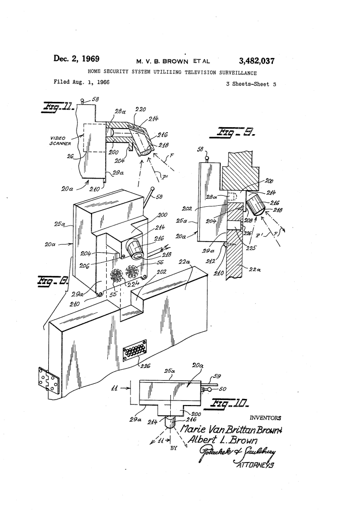
In a secondary embodiment, the patent introduces a non-motorized, stationary cabinet (20a) suitable for standardized installations:
- Over-Door Mounting Arm (200): A tubular bracket arm seats into a top door notch (202) and anchors via a front flange (204).
- Periscopic Optical Barrel (214): Houses a downwardly angled lens (218) and a 45-degree mirror (220) that bends the external line of sight directly into the horizontal camera barrel (28a).
- Full-Field Coverage: Captures the full exterior approach area optically, eliminating the drive motors, worm gears, and moving cabinet track while retaining complete audio, lock release, and alarm operations.
Historical and Scientific Impact
The Brown patent is universally recognized as the foundational architecture of modern home automation, closed-circuit television (CCTV) security, and smart video doorbells:
- Origin of Modern Video Intercoms: This patent established the fundamental operational sequence later popularized by commercial video intercoms, apartment buzzer systems, and connected video doorbells.
- Pioneering Remote Access: The remote unbolting mechanism introduced wireless residential access control decades ahead of modern electronic smart locks.
- Central Station Dispatch: The inclusion of an emergency relay communicating directly with a police or guard dispatch center anticipated the structure of the modern home alarm monitoring industry.
About the Inventors: Marie Van Brittan Brown & Albert L. Brown
- Marie Van Brittan Brown (1922–1999): An African American nurse and inventor born in Queens, New York. Frustrated by delayed police responses in her neighborhood during irregular work shifts, she designed and prototyped the security apparatus to give residents autonomous control over their personal safety. Her visionary work earned her recognition from the National Scientists Committee and national media coverage.
- Albert L. Brown (1916–1993): An electronics technician who collaborated closely with Marie to engineer the circuitry, RF signal modulators, frequency-selective relays, and electromechanical drives detailed in the patent.
Summary of Claims
The patent explicitly claims:
- A residential security system comprising an entrance door with a plurality of vertically spaced windows covered by pivotally supported protective plates.
- A movable cabinet containing a video scanning device mounted on vertical gear tracks at the door.
- Motor drive means inside the cabinet to move the scanner vertically past the windows, deflecting each protective plate in turn.
- A video signal transmitter within the cabinet to broadcast the exterior picture to a remote indoor location.
- Radio transmitter and receiver control means configured to selectively activate the drive motors from the remote station in response to received radio signals.
