
The Paul E. Williams Helicopter Patent (No. 3,065,933), granted on November 27, 1962, represents a radical attempt to rethink helicopter aerodynamics. Williams’ goal was to solve three primary headaches of helicopter design: vibration, high torque, and the mechanical complexity of cyclic pitch control.
1. The Core Innovation: Aerodynamic Cyclic Control
In a traditional helicopter, the pilot uses a “swashplate” to change the pitch of each blade as it spins (cyclic pitch). This is necessary because the blade moving forward (advancing) has more lift than the blade moving backward (retreating), which would otherwise cause the helicopter to roll over.
Williams claimed his rotor could eliminate this mechanical complexity through blade geometry alone.
- The Theory: By using a unique blade shape, he sought to create a “uniform distribution of air” through the rotor disk.
- The Result: He argued this nullified the “upstream-downstream” effect, making mechanical cyclic pitch unnecessary and resulting in a much quieter, smoother aircraft.
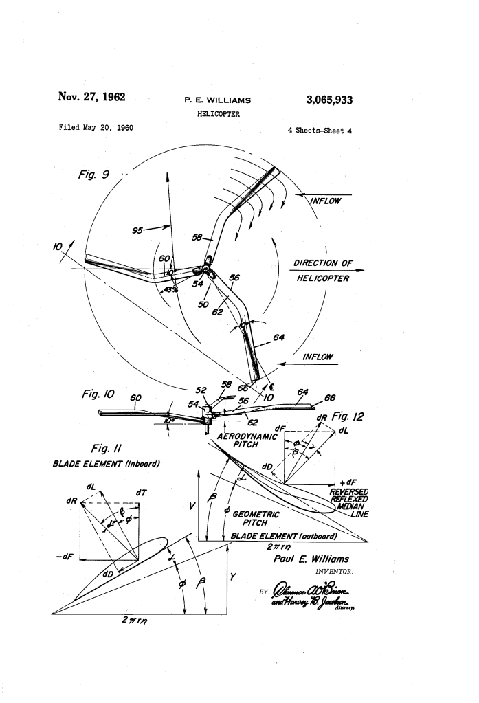
2. Blade Design: Inboard vs. Outboard
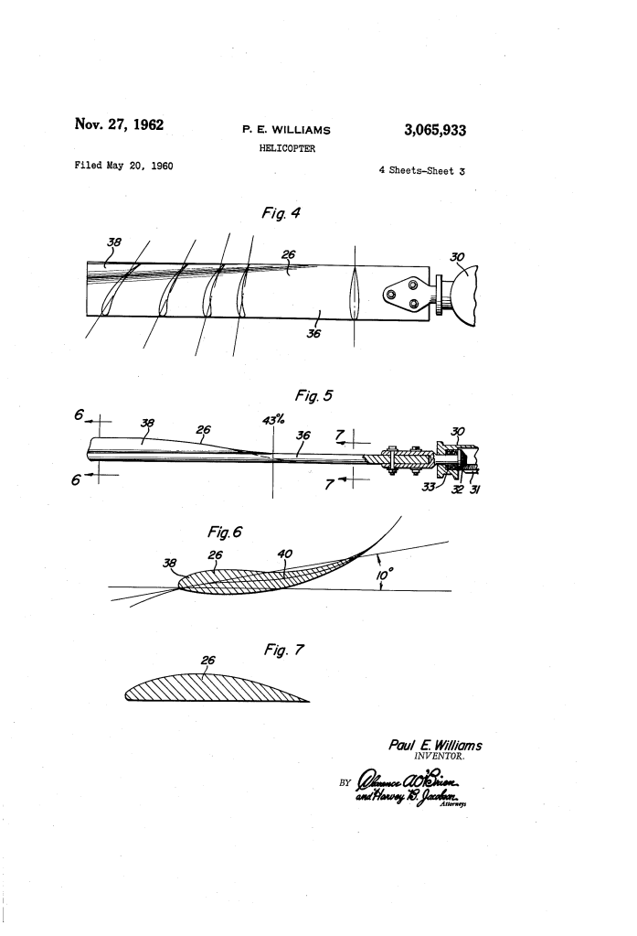
The patent divides the rotor blade into two distinct functional zones at the 43% station (43% of the way from the hub to the tip):
| Section | Location | Profile & Function |
| Inboard | Root to 43% | Conventional Airfoil. Provides the primary downwash and lift. It has a positive angle of attack. |
| Outboard | 43% to Tip | Reflexed/Reversed Median Line. This section has a negative angle of attack (inverted airfoil). It is designed to curve expansion waves inward. |
The “Infinite Aspect Ratio” Effect
Williams designed the tips to prevent tip turbulence. By equalizing the pressure on the top and bottom of the blade tip (destroying the vacuum), the air doesn’t “roll” over the edge. This creates what he called an infinite aspect ratio effect, significantly reducing drag and noise.
3. Torque Elimination
One of the most ambitious claims of the patent is the elimination of the tail rotor.
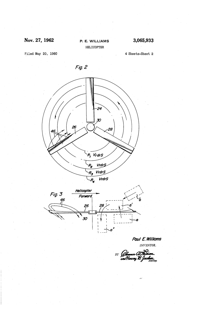
- Vector Balancing: In the outboard section, because of the negative angle of attack, the lift vector (dL) is inclined forward.
- Counter-acting Force: This creates a force component (dF) in the direction of rotation, which theoretically cancels out the drag forces of the inboard section.
- No Tail Rotor: If the aerodynamic drag of the blades is neutralized, there is no “torque” trying to spin the fuselage in the opposite direction, meaning no heavy anti-torque rotor or secondary engine is needed.
4. Advanced Geometry: Dihedral and Vertical Spacing
In his improved version (Figures 9–10), Williams added even more complexity:
- Vertical Gradient: Each of the three blades is mounted on the hub at a different height. They travel in separate horizontal planes. This was intended to eliminate “interplane effect” (interference between blades).
- Sweep Forward/Back: The inboard section is swept forward 10°, while the outboard section is swept back 10°. This creates a time lag in the airflow, allowing the air to “organize” and be induced downward more efficiently.
- Dihedral Angle: The inboard sections are angled upward, providing natural stability similar to the wings of a fixed-wing airplane.
5. Auxiliary Systems: The Duct and Fin
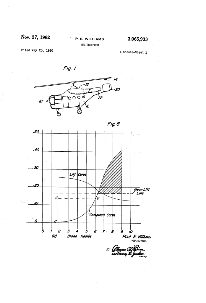
While the rotor was meant to be self-stabilizing, Williams included an optional longitudinal duct (16):
- Scoop: It catches the downwash from the rotor.
- Yaw Control: This air is blown over a vertical fin (20) at the rear. This provides steering (yaw control) and forward thrust without needing a traditional tail rotor.
Summary of Performance Claims
Williams claimed that compared to a standard helicopter, his design achieved:
- Lift Coefficients: Up to 3.00 (standard helicopters were typically around 0.5 to 1.0).
- Efficiency: Power requirements were reduced to between 38% and 93% of a standard helicopter.
- Stability: A reduction in “ground effect” dependency, allowing for more stable flight at various altitudes.
