
The document describes a Heating Apparatus invented by Benjamin F. Jackson of Cambridge, Massachusetts, and patented on March 1, 1898 (Patent No. 599,985). The invention is primarily designed for heating water to circulate through a system of radiators (hot water heating), but it can also be adapted for generating steam.
Inventor Background: Benjamin F. Jackson
Benjamin F. Jackson was an inventor specializing in thermal engineering and utility systems. His invention demonstrates a focus on efficiency and automation in domestic and commercial heating, specifically by optimizing the use of gaseous fuel (gas burners) to heat water or generate steam.
Invention and Mechanism
The apparatus is a high-efficiency gas boiler that uses a dome-shaped reservoir and internal conduits to maximize heat transfer while maintaining a controlled, airtight combustion environment.
1. Boiler and Heating Chamber
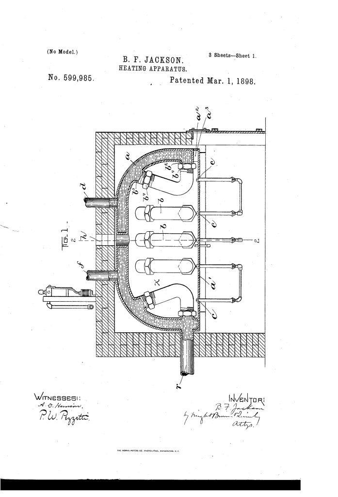
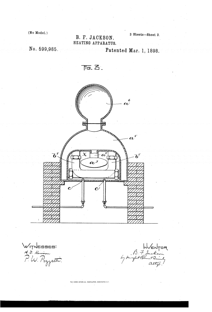
- Water-Reservoir/Boiler ($a$): Composed of two dome-shaped shells separated by an intervening water-space. The inner wall encloses a heating-chamber ($x$).
- Flue ($h$): A single outlet at the central upper portion of the dome for the escape of combustion products.
- Closed Bottom: A horizontal plate ($a’$) joins the base of the dome, forming the bottom of the heating-chamber ($x$). This bottom is preferably joined air-tight to the dome.
- Function: This air-tight sealing prevents the admission of cold air into the heating-chamber, except where intended, which prevents cold air currents from disturbing the flames and greatly contributes to the effectiveness and economy of the apparatus.
2. Internal Conduits (Heat Exchange) (Key Innovation)
- Elbow-Shaped Conduits ($b$): A series of thin-walled, elbow-shaped tubes (preferably copper) located inside the heating-chamber ($x$).
- Connection: Each conduit has a horizontal arm connected to the lower portion of the dome and a vertical arm connected to the upper portion of the dome.
- Function: These conduits hold water and are completely immersed in the hot products of combustion, serving as highly efficient internal heat exchangers to rapidly transfer heat to the circulating water.
3. Gas Burner System
- Burner-Tubes ($c$): Located directly under the horizontal arms of the conduits ($b$). The burner-tubes pass through and closely fit orifices in the air-tight bottom plate ($a’$).
- Function: The tubes are arranged to direct the flames of the gaseous fuel directly against the horizontal arms of the conduits. Because burners are placed only under the conduits and not under the empty spaces between them, the heat application is more direct and efficient, reducing wasted heat.
- Bunsen Principle: The burner-tubes ($c$) have air-inlets and gas-inlet pipes ($c^{2}$), functioning on the principle of the Bunsen burner to pre-mix gas and air for clean combustion.
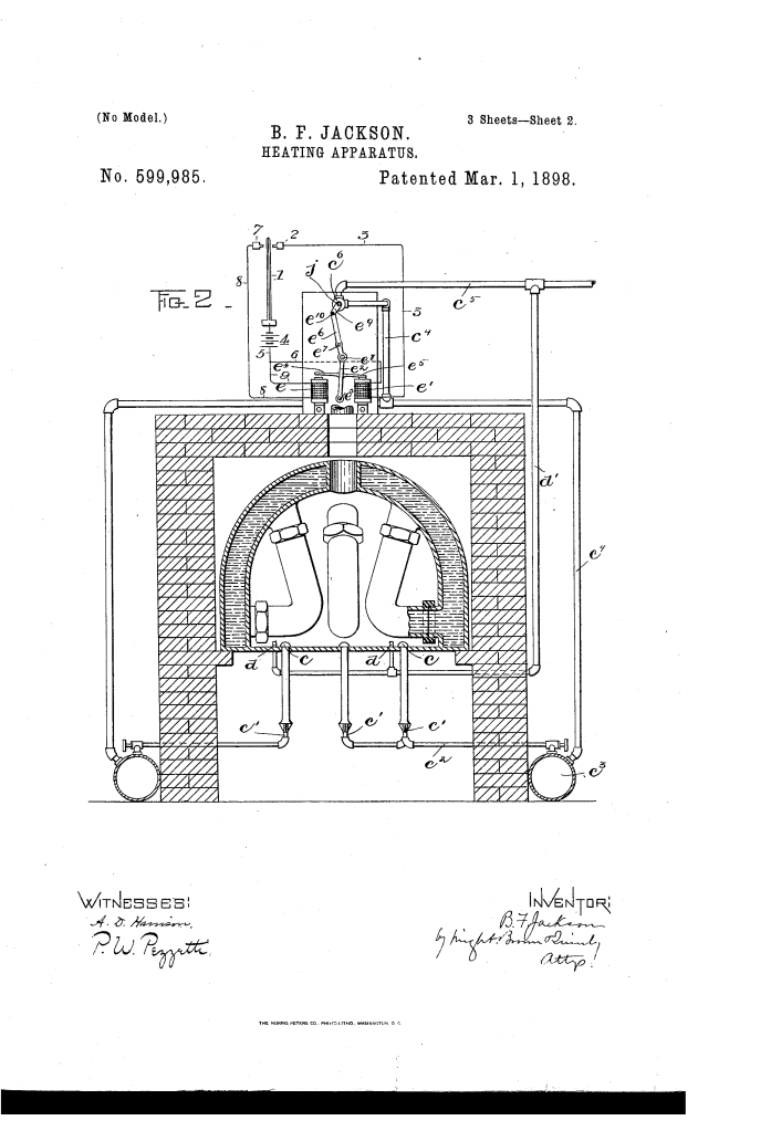
- Igniting-Burners ($d, d’$): Small, independent igniting-burners supplied by a separate gas pipe are located near the main burner-tubes.
- Function: These smaller burners are always on (not shut off by the main cock $c^{3}$) and are ready to reignite the main burners ($c$) whenever the gas is automatically turned back on.
4. Automatic Control
- Thermostatic Control: The main gas cock ($c^{3}$) is arranged to be closed automatically by a thermostatic device.
- Electromagnet Actuation: Two electromagnets ($e, e’$) are wired in independent circuits connected to a thermostat (1) in the heated apartment. One magnet closes the gas cock when the temperature rises, and the other opens it when the temperature falls.
Concepts Influenced by This Invention
Jackson’s heating apparatus influenced subsequent boiler design by establishing principles for high-efficiency, closed-system gas combustion and internal heat exchange.
- Internal Heat Exchanger Conduits: The concept of running elbow-shaped conduits ($b$) within the combustion chamber to rapidly heat the fluid is a key element of modern water-tube and fire-tube boilers , maximizing the surface area exposed to the flame and heated gas.
- Sealed/Controlled Combustion Chamber: The airtight design that prevents the uncontrolled admission of cold air influenced the engineering of modern high-efficiency condensing boilers and furnaces , which use sealed, forced-draft combustion chambers to optimize the air/fuel ratio and prevent flame disturbance.
- Automated Pilot/Relight System: The design’s use of independent, always-on igniting-burners ($d, d’$) to reliably reignite the main burners ($c$) after a thermostatic shut-off influenced the design of all modern gas appliances (water heaters, furnaces, ovens) that use pilot lights or electronic spark igniters to ensure safe, automatic relighting.
- Zoned/Thermostatic Control: The system’s use of thermostats and electric circuits to automatically modulate the main fuel supply based on ambient temperature influenced the development of modern centralized heating controls and zoned climate management systems.
