
Headlamp Rim Remover (Paul D. Burgin, No. 1,788,507)
The 1931 patent by Paul D. Burgin of Kansas City, Missouri, describes a specialized tool for automotive maintenance: the Headlamp Rim Remover (Patent No. 1,788,507). In the early 20th century, automobile headlamp rims were often secured by friction or bayonet-style locking mechanisms. Over time, road grime, rust, and heat would cause these rims to stick so tightly that they could not be removed by hand. Burgin’s tool provided the leverage and grip necessary to unlock these rims without damaging the vehicle’s finish.
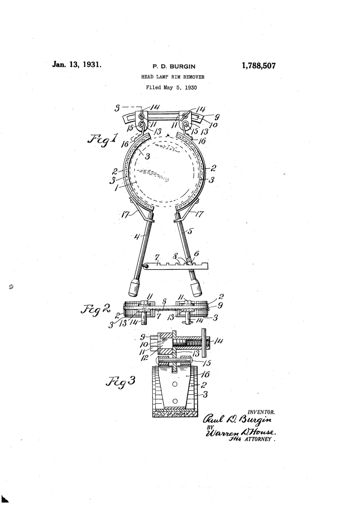
1. Gripping Mechanism and Surface Protection
The tool is designed around two mirrored gripping members that embrace opposite sides of the headlamp rim.
- Resilient Metal Strips (2): The core of each gripper is a flexible, resilient strip of metal that can contour to the circular shape of the lamp.
- Soft Padding (3): To prevent metal-on-metal contact, the inner side of each strip is lined with a pad made of felt or canvas. This ensures the tool grips the rim securely but will not scratch the chrome or paint.
- Braces (17): To ensure the force from the handles is distributed across the entire strip (rather than just bending the metal where it attaches to the handle), Burgin added reinforcement braces to keep the strips from deforming under pressure.
2. Adjustability for Various Diameters
Because car headlamps varied in size, Burgin engineered the tool to be universally adjustable.
- Slotted Link Member (9): The two grippers are connected by a metal bar featuring a long longitudinal slot (10).
- Slidable Supports: The grippers are attached to this link via bolts (11) that can slide along the slot.
- Hinged Connection (16): The metal strips are not fixed rigidly; they are hinged to the supports. This allows the grippers to “swing” open or shut to accommodate the depth and curve of different headlamp designs.
- Locking Nuts (14): Once the user slides the supports to the correct width for a specific car, they tighten the nuts to lock the width in place.
3. Leveraged Turning System
The removal process relies on a heavy-duty handle system that provides mechanical advantage.
- Handles (4 & 5): Each gripper has its own handle. When the user squeezes these handles together, it tightens the grip of the felt pads onto the headlamp rim.
- Ratchet Member (7): To assist the user, one handle features a notched ratchet bar that slides through a slot (6) in the opposite handle.
- Function: The notches (8) allow the tool to “lock” its grip onto the rim. This frees the user’s hands to focus on the twisting motion required to unlock the rim from the lamp housing, rather than just struggling to keep the tool from slipping.
4. Operation Summary
The technician uses the tool in three primary stages:
- Sizing: Loosen the nuts (14), slide the grippers to match the headlamp’s diameter, and retighten.
- Clamping: Place the tool over the rim and squeeze handles (4) and (5). Engage the ratchet (7) to maintain a firm, non-slip hold.
- Removal: Swing the entire tool assembly in a twisting motion to free the rim from its locked position.
Engineering Significance
Paul Burgin’s invention addressed a specific frustration of the “Great Depression” era mechanic. As automobiles became more streamlined, headlamp housings became more integrated and harder to service.
- Damage Prevention: By using felt-lined flexible strips instead of standard pliers or wrenches, the tool protected the aesthetic value of the car.
- Mechanical Advantage: The long handles transformed a difficult hand-twisting task into a high-torque mechanical operation.
- Versatility: The slotted-link design made it a “one size fits all” tool for the diverse automotive market of the 1930s.
