
Gaseous Discharge Device (1963)
U.S. Patent No. 3,072,865, granted on January 8, 1963, to Louis W. Roberts and assigned to Microwave Associates, Inc., describes an advanced TR (Transmit-Receive) switching tube. This device solved a major limitation in early radar systems: the narrow frequency range (bandwidth) of standard gas-filled switching tubes.
The Problem: Resonant Limitations
In 1950s radar technology, TR tubes were used to protect sensitive receivers from the high-power pulses of the transmitter.
- Resonant Iris Problem: Most TR tubes used “resonant iris” structures—metal plates with holes tuned to a specific frequency. Like a tuning fork, they only worked well at one “center” frequency.
- Bandwidth Constraints: If the radar needed to shift frequencies to avoid jamming or improve resolution, the TR tube would fail to protect the receiver or block too much signal.
The Innovation: Capacity-Loaded Ridge Waveguide
Roberts replaced the restrictive resonant irises with a ridged waveguide design. This approach uses physical geometry rather than tuned circuits to create the conditions necessary for a gaseous discharge.
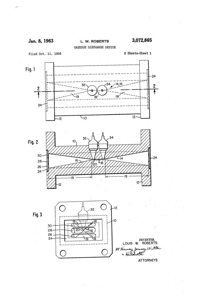
1. The Pyramidal Ridges (14 & 16)
Inside a rectangular waveguide section (10), Roberts placed two opposed, pyramid-shaped ridges.
- The Gap (20): These ridges culminate in a sharp “knife edge” (18), creating a very narrow central gap.
- Potential Gradient: By narrowing the space, the electric field becomes highly concentrated at the gap. When a high-power microwave pulse enters, the potential gradient becomes so intense that it instantly ionizes the gas in the tube, creating a short circuit that reflects the energy away from the receiver.
2. Tapered Transition Ramps (19)
To prevent the ridges from reflecting the desired signal, Roberts added ramp-like sections. These ramps gradually transition the impedance from the open waveguide to the narrow gap, allowing signals to pass through with very low loss (insertion loss) when the gas is not ionized.
Key Features and Components
| Component | Description | Function |
| Triple Iris Window (24) | A window with three slots (one wide center, two narrow outer). | Seals the gas inside while allowing a wide range of microwave frequencies to pass. |
| Keep-Alive Electrodes (32, 34) | Electrodes that maintain a small, constant “glow discharge.” | Provides a ready supply of electrons so the main discharge triggers instantly when a pulse arrives. |
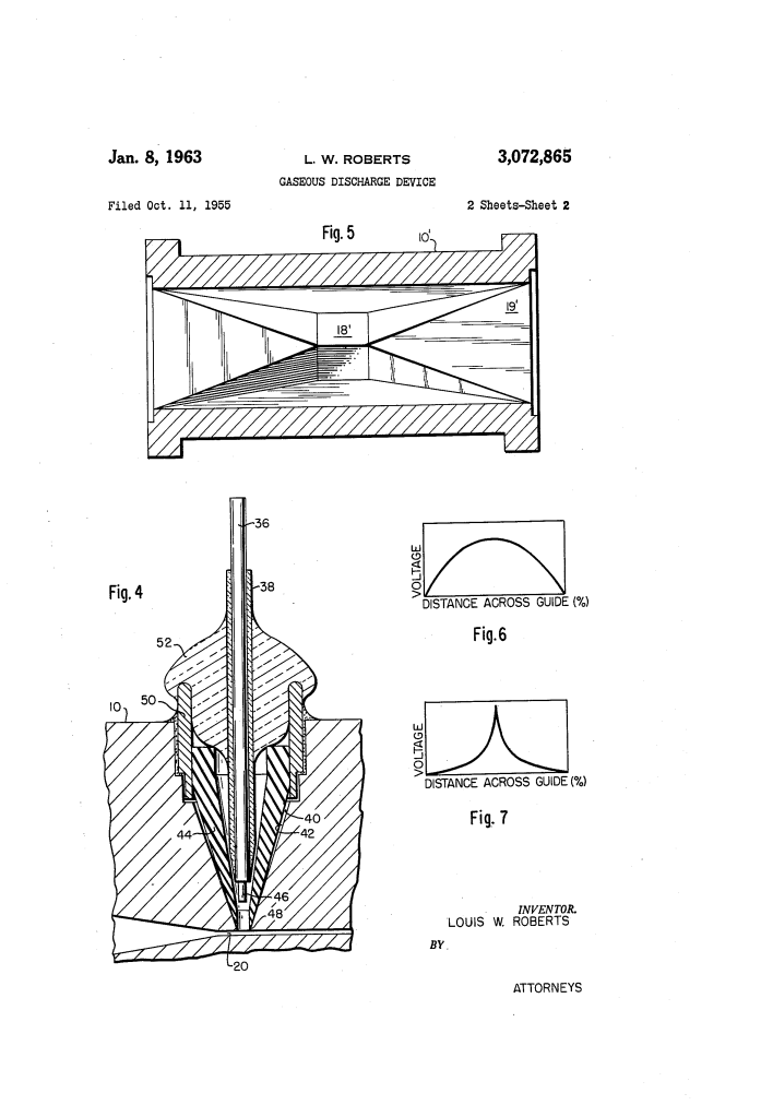
| Hardened Tips (46) | Electrode tips made of stainless steel or reduced titanium dioxide. | Resists “sputtering” (erosion) caused by ion bombardment, extending the life of the tube. |
| Dielectric Insert (44) | A preformed insulating cone inside the electrode chamber. | Forces the discharge into a single, consistent path length for more reliable switching. |
Scientific Significance: Field Intensity
Roberts used the geometry of the ridges to distort the standard TE_10 mode of the waveguide.
- In a normal waveguide, the voltage follows a simple cosine curve across the width.
- In Roberts’ device, the ridges concentrate the field toward the center. Mathematically, the field intensity becomes a function of cos^n, where n > 2. This concentration is what allows the tube to “break down” and protect the system across a massive frequency range (e.g., 8,000 to 12,400 MHz) without needing to be retuned.
Practical Impact
This invention allowed radar systems to be much more versatile. Because the tube could handle up to 100 kilowatts of peak power over a 4,000 MHz bandwidth, it was ideal for high-performance military and commercial radar that required frequency agility and long-term reliability.
