
Gas-Burner (Benjamin F. Jackson, No. 622,482)
The patent by Benjamin F. Jackson of Cambridge, Massachusetts, describes an improvement in a Gas-Burner (Patent No. 622,482, 1899) for consuming mixed air and gas. The burner is specifically designed for systems where air is supplied under pressure (forced-air burners). The objective is to ensure that all parts of the burner receive an equal amount of air, maintaining an even combustion across the entire burner, leading to higher efficiency and longer life.
Inventor Background: Benjamin F. Jackson
Benjamin F. Jackson was an inventor specializing in thermal and combustion engineering, previously patenting a high-efficiency water heater (No. 599,985). This patent builds on his expertise by addressing a persistent problem in forced-air systems: uneven fuel distribution, which causes premature component burnout and uneven heating.
Invention and Mechanism
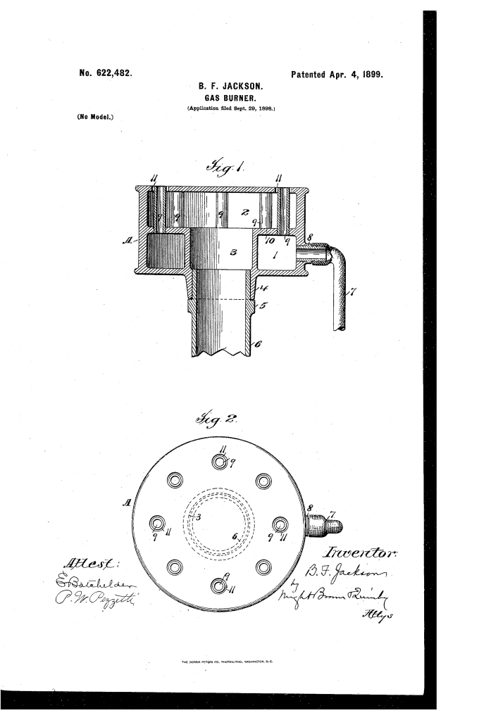
The invention is a single casting that uses a central air intake and internal geometry to create a plenum that ensures uniform air distribution to multiple burner tubes.
1. Dual-Chamber Structure
- Casting (A): The burner is formed from a single metal casting separated into two superposed chambers by a web (10).
- Gas Chamber (1): The lower chamber, annular in form, receives gas from a supply pipe (7).
- Air Chamber (2): The upper chamber, into which air is forced under pressure.
2. Uniform Air Distribution (Key Innovation)
- Central Air Inlet (Tube 3): The air under pressure is admitted into the air chamber (2) through a central tube (3) that rises from the air supply pipe (6).
- Flow Dynamics: The air is directed vertically into the chamber, where it first impinges against the top wall of the air chamber (2) and then flows laterally and evenly in all directions toward the burner tubes (9).
- Result: This balanced flow ensures that an equal amount of air is supplied to every burner tube, guaranteeing uniform combustion and preventing hotspots that cause premature burnout.
3. Burner Tubes and Mixing
- Burner-Tubes (9): Short tubes leading from the gas chamber (1), passing through the air chamber (2), and exiting through small orifices (11) in the top wall.
- Mixing Point: The orifices (11) are slightly larger than the burner tubes (9), leaving a space around them.
- Function: The air under pressure is forced out through this space, mixing with the gas as it issues from the tube (9). This forms the high-intensity, even flame.
Concepts Influenced by This Invention
Jackson’s burner influenced subsequent designs for industrial combustion and chemical mixing systems by pioneering the centralized plenum concept for uniform fluid distribution.
- Centralized Plenum/Uniform Distribution: The core principle of admitting a fluid (air) under pressure centrally into a closed chamber (plenum) so that it is forced to distribute equally and radially to multiple outlets influenced the design of:
- Industrial Burner Systems: All subsequent multi-port forced-air or forced-draft burners for furnaces, boilers, and kilns.
- Chemical and Fluid Manifolds: Distribution systems in industrial process equipment that require uniform delivery of gas or fluid to multiple reaction chambers or nozzles.
- Component Life Extension: The explicit objective of achieving even combustion to extend the life of all components influenced the engineering of high-temperature industrial equipment, where thermal stresses must be managed to reduce the cost of maintenance and replacement.
- In-Situ Mixing: The design that routes the gas through tubes inside the air chamber, ensuring mixing occurs only at the final outlet orifice, influenced the engineering of precise Bunsen-style mixing systems for laboratories and industry.
