
Fluid Joint, Asa J. Taylor (1948)
Patented in January 1948, this invention by Asa J. Taylor (U.S. Patent No. 2,434,629) addressed a fundamental mechanical challenge: how to pump liquid (like oil or water) through a moving hinge without using external hoses that could kink, leak, or burst.
Taylor’s Fluid Joint reimagines the standard hinge pin as a high-pressure conduit. By integrating the fluid path directly into the hardware of the joint, he created a “hose-less” hydraulic system. This design was particularly vital for heavy-duty machinery like hydraulic jacks and industrial cranes, where constant movement often wears out traditional flexible tubing.
The “Why”
In the 1940s, hydraulic systems relied heavily on external rubber or metal hoses to span moving joints. These hoses were the “weak link”—they were prone to snagging on equipment or developing fatigue cracks from repeated bending.
- The Problem: Moving parts need fluid, but the “bridge” (the hose) between those parts is fragile.
- The Solution: Taylor moved the fluid path inside the Hinge Pin (20). By making the pivot point itself the pipe, he eliminated the need for external hoses, creating a compact, “leak-proof” joint that can rotate infinitely while maintaining a constant flow of high-pressure fluid.
Inventor Section: Engineering Philosophy
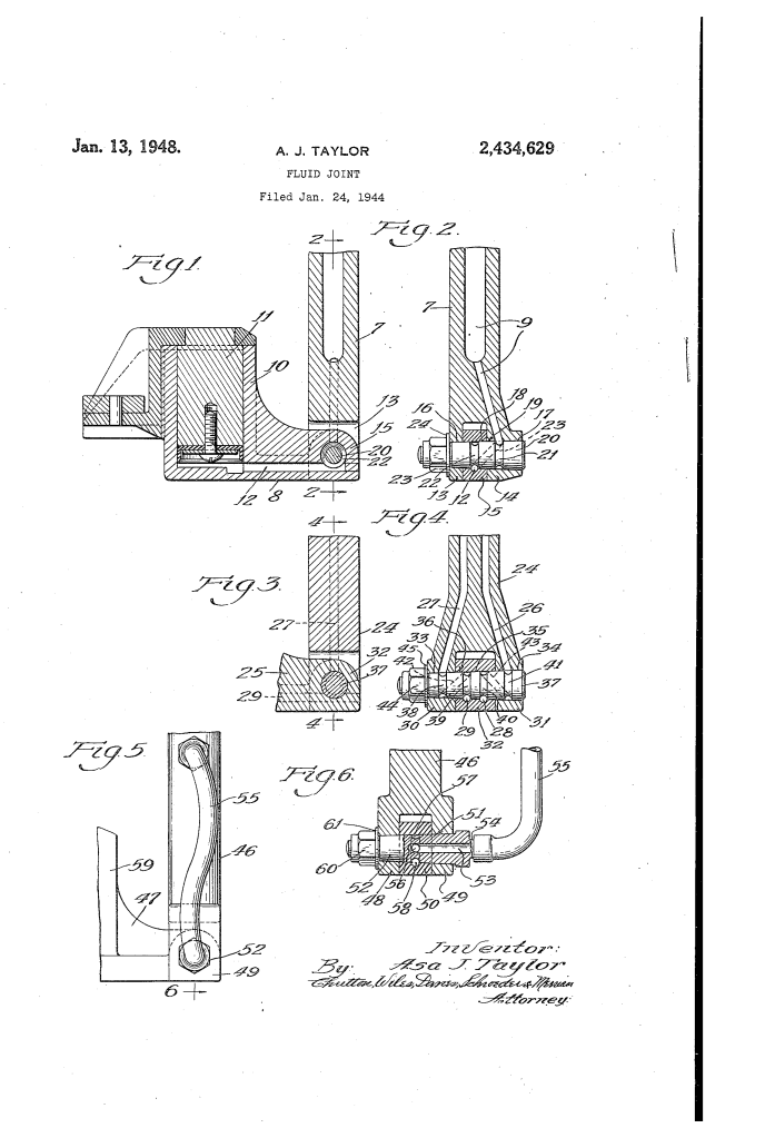
Asa J. Taylor’s philosophy was Coaxial Integration. He believed that a single component should perform two distinct roles: mechanical support and fluid transport. His design utilizes a Tapered Pin (20) that fits into a matching tapered hole. This geometry allows the operator to tighten a nut (23), wedging the pin into the socket to create a “metal-to-metal” seal that is tight enough to hold hydraulic pressure but smooth enough to allow the hinge to swing.
Key Systems Section
1. The Groove-and-Channel System
This is the “internal plumbing” of the hinge pin.
- Arcuate Grooves (21, 22): Taylor carved circular channels around the circumference of the pin. These act as “manifolds.” Because they go all the way around, they stay aligned with the fluid passages (9, 12) in the hinge legs regardless of the angle of the joint.
- Cross-Groove (23): A longitudinal slot connects the two circular grooves.
- The Flow Path: Fluid enters a leg of the hinge, fills the first circular groove, travels down the cross-groove, and exits through the second circular groove into the other moving part of the machine.
2. The Tapered Seal Mechanism
High-pressure hydraulic fluid will escape through any microscopic gap. Taylor solved this with precision geometry.
- The Taper (19, 20): The pin and the holes are slightly cone-shaped.
- Self-Locking Nut (23): By tightening the nut at the small end of the taper, the pin is pulled deeper into the socket.
- The “Fluid-Tight” Joint: This creates an incredibly tight fit that acts as a natural gasket. It prevents leakage even under the high pressures required to lift heavy loads with a hydraulic ram (11).
3. The Dual-Course Joint (Multi-Path)
In Figure 3 of the patent, Taylor shows a “Four-Groove” version.
- Complex Flow: This version has four separate circular grooves (38, 39, 40, 41) and two internal cross-channels.
- The Purpose: This allows for a “supply” line and a “return” line to pass through a single hinge pin simultaneously without mixing. This is essential for modern hydraulic cylinders that need to both extend and retract under power.
Key Components of the Taylor Joint
| Part Number | Component | Function |
| 7 & 8 | Hinged Members | The two moving parts (e.g., the base and the arm of a jack). |
| 9 & 12 | Passages | Internal tunnels for fluid within the metal members. |
| 20 | Tapered Hinge Pin | The “heart” of the joint; provides the pivot and the fluid path. |
| 21 & 22 | Endless Grooves | Ensure fluid connection at any rotational angle. |
| 23 | Self-Locking Nut | Provides the “squeeze” to prevent leaks at high pressure. |
Significance
Asa J. Taylor’s invention was a milestone in Fluid Power Engineering:
- Safety & Reliability: By removing external hoses, Taylor made hydraulic machines safer and less prone to sudden failure in the field.
- Compact Design: This allowed for much smaller, sleeker hydraulic tools, as there was no “hose clutter” around the pivot points.
- Foundation for Modern Hydraulics: The concepts of “rotary unions” and “swivel joints” used in modern excavators and robotic arms today are direct descendants of Taylor’s 1948 tapered-groove design.
Final Insight: Taylor’s joint is a reminder that the most elegant solutions are often “hidden” inside the machine. While everyone else was trying to make better hoses, Taylor was busy making the hose unnecessary.
