

Image Converter for Detecting Electromagnetic Radiation Especially in Short Wave Lengths (1969)
U.S. Patent No. 3,478,216, granted on November 11, 1969, to George R. Carruthers, addresses a fundamental limitation in space astronomy and electro-optical detection: imaging the far-ultraviolet (FUV) spectrum without signal attenuation or spectral cutoff caused by optical windows.
Before this invention, ultraviolet detectors relied on semi-transparent photocathodes deposited on the inside surfaces of transmission windows made of materials like lithium fluoride. These conventional tubes suffered from low quantum efficiency, severe short-wavelength cutoff, and window degradation. Dr. Carruthers, an astrophysicist at the U.S. Naval Research Laboratory (NRL) in Washington, D.C., developed a windowless, magnetically focused image converter featuring internal reflective optics and an open, front-illuminated solid photocathode designed to operate directly in the ambient vacuum of space.
The Core Design: The Windowless Internal-Optic Converter
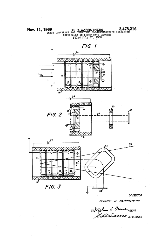
The innovation of the Carruthers converter is its window-free, front-surface configuration. Instead of passing through a transmissive glass or crystal barrier, incoming far-ultraviolet radiation enters an open aperture and reflects directly off internal optics onto a solid opaque photocathode.
- Parabolic Primary Mirror with Central Aperture (13, 21)
- Parallel far-ultraviolet light rays (12) enter the open tube and strike a concave primary mirror (13).
- The mirror focuses the incoming rays forward onto the face of an axially aligned photocathode (15).
- A central axial aperture (21) bored through the middle of the mirror provides an unobstructed exit path through which emitted electrons travel toward the rear image plane.
- Opaque Front-Surface Photocathode (15)
- Built on a solid base (such as glass coated with conductive silver and sensitized with cesium iodide), the photocathode emits electrons from the very same front surface upon which the light impinges.
- This front-surface emission achieves dramatically higher quantum efficiency than semi-transparent transmission films and completely eliminates the short-wavelength cutoff imposed by solid optical entrance windows.
- Coaxial Electric and Magnetic Focusing Fields (16, 17, 18)
- A high-voltage electrostatic gradient (around negative 20 kV relative to ground) is generated along the tube by a voltage divider string of resistors (17) connected across spaced accelerator rings (16).
- An external cylindrical solenoid coil (18) produces a uniform axial magnetic field parallel to the electric field.
- This combined electromagnetic field accelerates the photoelectrons (14) rearward and focuses them through the central mirror aperture (21) onto the image recording plane with 1:1 optical fidelity and high resolution across the entire field of view.
How the Apparatus Functions
The imaging sequence operates entirely within the natural vacuum environment of high-altitude sounding rockets or orbiting satellites:
| Step | Action | Functional Purpose |
| 1. Direct Optical Collection | Parallel far-ultraviolet light (12) enters the open tube and strikes the concave reflective mirror (13). | Gathers and focuses incoming short-wavelength radiation without transmissive window losses. |
| 2. Photoelectric Conversion | Focused rays strike the front surface of the solid photocathode (15). | Emits a spatial stream of photoelectrons (14) directly into the tube interior. |
| 3. Electromagnetic Acceleration | An axial electrostatic gradient (rings 16, resistors 17) and uniform magnetic field (solenoid 18) guide the electron stream. | Accelerates and magnetically focuses the electrons through the mirror aperture (21) toward the image plane. |
| 4. Detection / Recording | Accelerated electrons impact an electron-sensitive nuclear track emulsion (22, 23) or phosphor screen. | Records high-resolution electron images directly on film or converts them into visible light pulses for video transmission. |
Technical Components
| Component | Function |
| Concave Mirror (13) | Internal focusing optic with an electrically conductive, grounded reflective surface and central aperture (21). |
| Solid Photocathode (15) | Front-surface photoemitter (typically silver/cesium iodide) biased at high negative potential (approx. -20 kV). |
| Accelerator Rings (16) & Resistors (17) | Spaced annular electrodes forming an axial voltage divider to create a uniform accelerating electrostatic field. |
| Solenoid Coil (18) | Cylindrical magnetic coil surrounding the tube assembly, energized by a DC source (24) to collimate and focus electrons. |
| Auxiliary Deflection Coils (25 / 32) | Secondary magnetic lens (25 in FIG. 2) or external Helmholtz coils (32 in FIG. 3) to guide or turn electrons 90 degrees off-axis. |
| Image Detector (22, 26, 35) | Nuclear track emulsion film, electron-sensitive target, or phosphor screen that records or displays the final image. |
Alternative Configurations: Off-Axis and Anti-Contamination Designs
The patent provides two alternative layouts to address specific operational challenges:
- Auxiliary Lens Focusing (FIG. 2): Incorporates an additional magnetic lens (25) outside the primary mirror assembly to refocus the photoelectron stream onto an external aligned target (26).
- 90-Degree Helmholtz Deflection (FIG. 3): Employs external Helmholtz coils (32) to steer the accelerated photoelectrons 90 degrees away from the optical axis onto an off-axis detector (35). This setup is tailored for reactive, cesium-activated photocathodes sensitive above 1800 Angstroms: because the photocathode cannot “see” the recording film, it prevents outgassing contaminants from the emulsion from impinging on and poisoning the photocathode surface.
Historical and Scientific Impact
Dr. George R. Carruthers’ invention was a milestone in observational astrophysics and space science:
- Foundation for Apollo 16: This patented electro-optical architecture formed the direct technological core of the Far Ultraviolet Camera/Spectrograph, deployed on the lunar surface during the Apollo 16 mission in April 1972.
- First Global Views of Earth’s Geocorona: From the Moon, Carruthers’ instrument captured the first comprehensive global ultraviolet photographs of Earth’s upper atmosphere, geocorona, and auroral belts.
- Discovery of Interstellar Molecular Hydrogen: The high quantum efficiency and window-free design enabled sounding rockets to detect molecular hydrogen in interstellar space, resolving a major missing-mass question in astrophysics.
- Government Title: The patent was assigned to the United States Government for royalty-free public service and defense use, reflecting its central importance to the Navy and NASA space programs.
About the Inventor: George R. Carruthers
Dr. George Robert Carruthers (1939–2020) was a pioneering African American astrophysicist, engineer, and inventor who spent a distinguished career at the U.S. Naval Research Laboratory.
- Academic Background: Born in Cincinnati, Ohio, and raised in Chicago, Carruthers earned his B.S. in aeronautical engineering, M.S. in nuclear engineering, and Ph.D. in aeronautical and astronomical engineering from the University of Illinois at Urbana-Champaign.
- Career and Honors: Serving as head of the Ultraviolet Measurements Branch at NRL, he was awarded the National Medal of Technology and Innovation by President Barack Obama in 2012 and was inducted into the National Inventors Hall of Fame in 2003.
- Educational Outreach: In addition to his aerospace instrumentation breakthroughs, Carruthers dedicated decades to science education, founding community science programs in Washington, D.C., and teaching earth and space science at Howard University.
Summary of Claims
The patent explicitly claims:
- An open, window-free electro-optical image converter configured for operation in the vacuum of space, comprising a concave focusing mirror, an aligned front-emitting photocathode, and an electron receiver.
- The arrangement where the mirror, photocathode, and electron detectors are open to ambient pressure, ensuring incoming radiation is completely free from window transmission.
- A magnetic field generator and electrostatic field generator surrounding the optics to focus emitted photoelectrons onto the electron receiving surface.
- A primary focusing mirror containing an axial aperture through which emitted photoelectrons pass to reach the image plane.
- Embodiments featuring auxiliary focusing coils, direct electron-recording emulsions, and off-axis Helmholtz steering coils to guide the electron beam.
