
Extension Step for Cars (1897)
U.S. Patent No. 574,969, granted on January 12, 1897, to Daniel L. White, addresses a common hazard and accessibility issue of late 19th-century rail travel: the large gap and height difference between train passenger car steps and ground-level station platforms.
When passenger cars stopped at rural or temporary stations without raised platforms, the bottom step was often too high off the ground for passengers to safely embark or disembark. White, an inventor from Cincinnati, Ohio, developed an automatically folding, multi-tier extension assembly that could be deployed to add extra steps to a train car’s fixed stairway when needed, and safely folded away when in motion.
The Innovation: The Rotational and Linkage Assembly
The core idea behind White’s invention is a multi-frame mechanism that uses gravity, lever arms, and pivotal joints to extend a single fixed flight of steps into an expanded, safe staircase without requiring complex, heavy machinery.
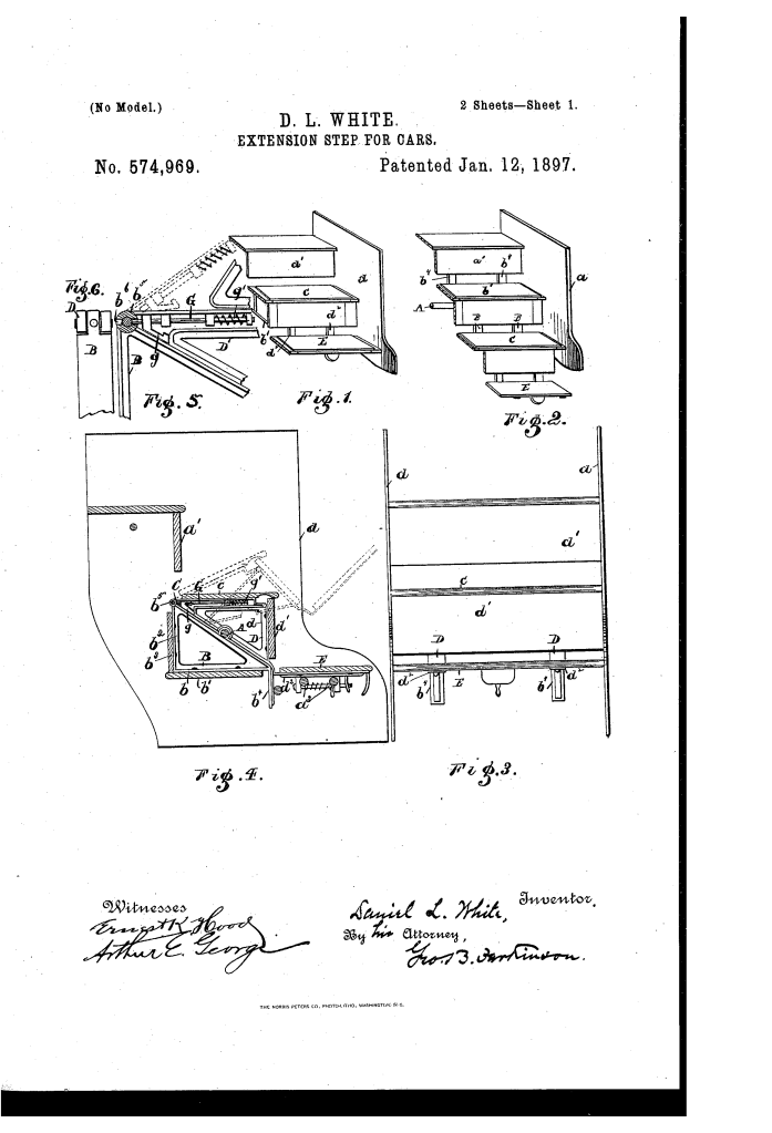
- The Triangular Pivot Frame (B)The upper moving section relies on right-triangular frames (B) pivoted at the center of their hypotenuses to a transverse shaft (A) mounted between stationary step-hangers (a).
- These frames support a step (b) and a rise-board (b’).
- The triangular design allows the frame to swing 180 degrees around shaft (A), moving step (b) into a horizontal position either above or below the main shaft.
- A projection (b”) contacts the stationary rise-board (a’) to stop the frame from swinging too far forward.
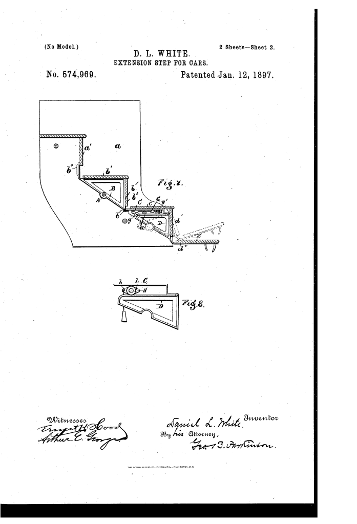
- The Intermediate Linkage Plate (C) and Lower Frame (D)Hinged to the outer joint (b”’) of frame (B) is a connecting plate (C), which carries its own step (c).
- Attached to the free end of plate (C) is a second triangular frame (D) carrying a lower step (E) and a rise-board (d).
- In the folded position, step (E) rests securely on transverse rods (a”) spanning between the main step-hangers.
How the Extension Mechanism Functions
Deploying and retracting the extension steps follows a continuous mechanical sequence driven by hand movement and locked automatically:
| Step | Action | Mechanical & Safety Purpose |
| 1. Extension | Conductor lifts frame (D) outward and downward. | Pulls plate (C) and rotates triangular frame (B) a half-turn around shaft (A). |
| 2. Deployment | Step (b) moves down into the old position of step (c); step (c) drops to the former position of step (E); step (E) extends to the bottom. | Expands the total flight downwards by multiple steps, reaching close to ground level. |
| 3. Auto-Locking | Frame (D) swings under cross-rods (a”) and engages catch (g) on sliding pin (G). | Forces sliding pin (G) into aperture (b””) on hinge (b”’), locking frame (B) and plate (C) rigid against weight loads. |
| 4. Automatic Folding | When unlocked, counterbalanced geometry automatically returns steps to collapsed position. | Prevents the steps from remaining extended and striking objects alongside the tracks. |
Inertia-Based Safety Release Mechanism
A major safety concern with extensible train steps was human error—if a train conductor forgot to manually fold the steps before departure, the protruding structure could strike trackside equipment, platforms, or switch boxes, causing a catastrophic derailment or structural damage.
White solved this with an ingenious vibration-sensitive automatic unlock device:
- An inertia plate (h) with pivoted arms is mounted between plate (C) and frame (D).
- One arm carries an integrated weight.
- When the train begins to move, the sudden jar or vibration from starting causes the weighted arm to swing.
- This movement forces plate (C) and frame (D) slightly apart, releasing locking pin (G) from aperture (b””) and disengaging the lock.
- Once disengaged, the properly balanced hinge assembly automatically folds back up into its retracted position under its own weight.
Key Mechanical Components
- Transverse Shaft (A): The primary support axle mounted between stationary step-hangers (a).
- Triangular Frame (B): Primary rotating frame carrying step (b) and rise-board (b’).
- Hinge End (b”’): The pivot point between frame (B) and plate (C), containing aperture (b””) for locking.
- Connecting Plate (C): Intermediate hinged support plate holding step (c).
- Lower Frame (D): Secondary frame holding lowest step (E) and rise-board (d).
- Sliding Pin (G): Spring-loaded (g’) locking bolt that secures the hinges in place during use.
- Inertial Weight Plate (h): Safety device that uses train movement vibration to unlock the mechanism automatically.
About the Inventor: Daniel L. White
Daniel L. White was an inventor residing in Cincinnati, Ohio, during the late 19th century—a major hub for railroad manufacturing and industrial design. His work reflected the era’s strong push toward improving passenger train safety, urban transport accessibility, and automated fail-safe transit hardware.
Summary of Claims
The patent explicitly claims:
- An extensible flight of steps featuring a step-frame pivoted to rotate above or below its pivot axis, coupled with a hinged second step-frame that swings into position as the first transitions.
- A spring-loaded sliding locking pin (G) activated directly by the movement of the secondary frame (D) to lock the hinged linkage rigid during use.
- An automatic inertia-based unlocking device with a weighted arm (h) designed to throw the frames apart and disengage the locking mechanism when subjected to the vibration of a starting train.
