
Exhaust Purifier (1968)
U.S. Patent No. 3,378,241, granted on April 16, 1968, to Rufus Stokes, describes an industrial exhaust purifier designed to eliminate toxic fumes, particulate matter, and noxious emissions from smokestacks and incinerators. Rufus Stokes, an inventor based in Chicago, Illinois, assigned the patent to R.S. Engineering Company, Inc.
This specific invention solved a persistent environmental health and engineering problem in industrial air sanitation: conventional wet scrubbers could capture large soot particles through water sprays and settling tanks, but routinely failed to trap microscopic particles. In earlier systems, microscopic soot and gaseous impurities became encapsulated in microscopic gas bubbles. These buoyant bubbles shielded the contaminants from the scrubbing liquid, floating them directly up to the surface where they burst and escaped into the atmosphere. Stokes designed an integrated, multi-tank recirculating system that uses mechanical backpressure, forced liquid agitation, and bubble-shearing impellers to scrub and capture fine particulate emissions.
The Core Design: Multi-Stage Recirculation and Bubble Shearing
The design operates on continuous wet scrubbing through four interconnected vessels: an exhaust induction tank, a surrounding recirculation tank, a subterranean baffled mixing tank, and a subterranean liquid settling tank.
Rather than allowing combustion gases to bubble passively through standing water, Stokes forced the gas-liquid mixture through high-velocity recirculating loops and mechanical disintegrator impellers.
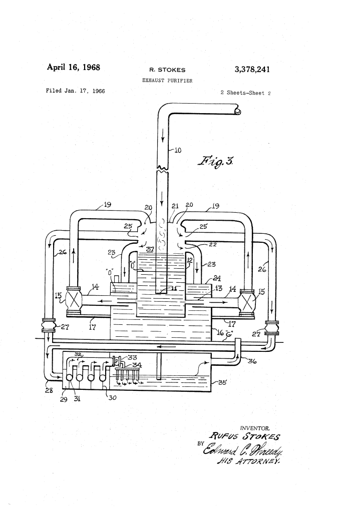
- Submerged Discharge and Pressure Barrier (10, 11, 37)Hot flue gas enters through exhaust stack 10, terminating in a downward opening 11 submerged beneath the liquid level of central induction tank 12. As agitator pumps 15 run, they draw liquid down to operating level O and blast an aerated liquid-fume slurry back into upper chamber 37 via overhead ports 20. This continuous overhead spray creates a physical pressure barrier across the fluid surface, preventing unwashed smoke from bypassing the water bath.
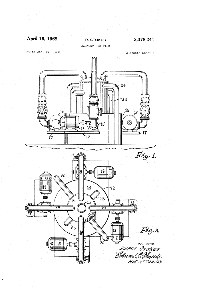
- Concentric Tank Agitation (12, 14, 16)Surrounding the lower end of induction tank 12 is annular recirculation tank 16. Radial ports 13 in the inner tank project into enlarged induction conduits 14, creating restricted venturi-style intakes. The agitator pumps pull simultaneously from both the inner smoke bath and outer fluid reservoir, mixing them into a homogenized slurry while recirculating conduits 23 shunt excess pressure from upper chamber 37 back into tank 16.
- Mechanical Bubble Disintegration (29, 30, 31)Blowers 27 draw the lighter, unprecipitated fumes and aerosol droplets from induction tank 12 into subterranean mixing tank 29. Divided into serpentine channels by opposing alternating baffles 30, the tank houses high-speed mechanical impellers 31. These rotating blades shatter the protective surface tension of micro-bubbles, stripping the gaseous envelope away from sub-micron particulates and forcing them into direct contact with the liquid medium.
How the Apparatus Functions
The process follows a continuous hydrodynamic sequence to isolate and wash combustion effluents:
| Step | Action | Operational Purpose |
| 1. Submerged Induction | Flue gases enter stack 10 and blast downward through submerged outlet 11 into the liquid bath of induction tank 12. | Traps coarse soot, ash, and water-soluble compounds in the primary liquid bath. |
| 2. Slurry Agitation | Agitator pumps 15 pull liquid and soot from ports 13 and conduits 14, forcing the slurry up lines 19 and out nozzles 20. | Creates a falling liquid curtain in pressure chamber 37 that acts as a downward pressure barrier over fluid level O. |
| 3. Pressure Shunting | Overpressure in chamber 37 bleeds through recirculating lines 23 into the top of surrounding tank 16. | Relieves backpressure while returning fugitive gases into the secondary water bath. |
| 4. Blower Extraction | Forced-draft blowers 27 pull aerosolized mist and light particulates through ports 25 and lines 26/28 into mixing tank 29. | Directs buoyant, bubble-encapsulated impurities into the secondary mechanical treatment stage. |
| 5. Mechanical Scrubbing | Rotating impellers 31 whip the gas-liquid stream against alternating baffles 30. | Pulverizes and disintegrates protective gas bubbles, driving fine particulates into permanent suspension. |
| 6. Final Quench & Exhaust | Exhaust pump 33 drives the scrubbed mixture through manifold 32 and discharge pipes 34 beneath the liquid in settling tank 35. | Submerges the cleaned gas under a final water barrier; purified, clear air exhausts out stack 36. |
Technical Components
- Exhaust Stack (10, 11): Primary industrial combustion flue entering vertically with a submerged outlet.
- Induction Tank (12): Circular inner containment tank partially filled with liquid, forming an upper pressure chamber 37.
- Radial Outlet Ports (13) & Intakes (14): Concentric restricted fluid passages linking the inner induction pool to outer tank 16.
- Recirculation Tank (16): Annular outer water jacket supporting service platforms 17, agitator pumps 15, and drive motors 18.
- Recirculating Conduits (19, 23): High-pressure pipe network creating the top-down liquid curtain and pressure-relief bypass lines.
- Draft Blowers (27) & Transfer Lines (26, 28): Industrial blowers extracting aerosolized fumes for underground treatment.
- Subterranean Mixing Tank (29): Heavy-duty baffled scrubber chamber placed below ground level G, containing alternating vertical baffles 30 and rotating impellers 31.
- Settling Tank (35) & Clean Exhaust Stack (36): Final wash pool receiving discharge from manifold lines 34 and releasing purified gas to the atmosphere.
Environmental and Industrial Impact
Stokes’s clean-air technology emerged at a critical moment when municipal smog and industrial pollution were drawing national scrutiny, leading directly to the passage of local air pollution ordinances and the federal Clean Air Act amendments of 1970.
- Micro-Particulate Capture: Overcame the core limitation of standard wet scrubbers by using mechanical impellers to destroy micro-bubbles that carry fine soot.
- Operational Scalability: Designed to support continuous variable loads; the system could start on four agitator pumps and maintain scrubbing efficiency on just two pumps during steady-state operations.
- Municipal and Heavy Industry Application: The compact above-ground footprint paired with sub-surface settling vessels made it suitable for municipal incinerators, metal foundries, commercial boiler plants, and residential apartment complexes.
About the Inventor: Rufus Stokes
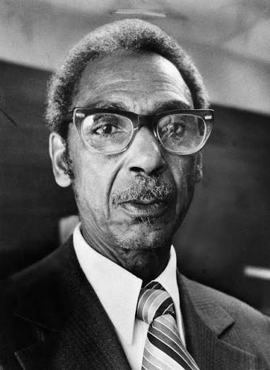
Rufus Stokes was an African American inventor and machinist born in Alabama who later relocated to Chicago, Illinois.
- Self-Taught Innovator: Despite having little formal engineering education, Stokes developed an advanced grasp of fluid mechanics, combustion processes, and machinery design while working in machining and maintenance roles.
- Air Purification Pioneer: In addition to this 1968 patent, Stokes continued refining wet-scrubbing technology, obtaining U.S. Patent No. 3,504,482 in 1970 for an improved particulate emission purifier.
- Clean Air Impact: His systems were demonstrated across Chicago and other industrial centers, earning praise from municipal health officials and environmental engineers for drastically reducing black smoke emissions and respiratory health hazards in urban neighborhoods.
Summary of Claims
The patent explicitly claims:
- An exhaust purifier combining a liquid-filled induction tank around a submerged smokestack, a surrounding recirculation tank, restricted fluid communication ports between the tanks, and external agitator pumps circulating a fumous-liquid slurry into an upper pressure chamber to form a pressure barrier.
- A pressure-relief shunt system using conduits between the upper pressure chamber and the outer recirculation tank to balance internal backpressure.
- Transferring the aerated exhaust via blowers into a multi-compartment baffled mixing tank equipped with high-speed impellers to mechanically scrub and disintegrate gas bubbles.
- An integrated subterranean settling tank submerged beneath a final liquid bath, receiving the scrubbed mixture through discharge pipes and releasing cleaned gas into the atmosphere via a final exhaust stack.
