
Emergency Landing Runway, Gus Burton, Patent No. 2,354,102
Patented in June 1944, during the height of World War II, this invention by Gus Burton of Wadley, Georgia, addresses a terrifying reality of early aviation: the “belly landing.” When an airplane’s landing gear failed to deploy or was shot away in combat, a pilot was forced to scrape the fuselage against hard earth or concrete, often resulting in fire, structural disintegration, and death.
Burton’s Emergency Landing Runway was designed to act as a “mechanical lubricant” for disabled aircraft. By embedding a series of specialized rollers into a permanent road surface, he created a landing strip that would allow a plane to glide to a stop on its underside without the friction-induced heat and shredding of a traditional runway.
The “Why”
In the 1940s, a disabled plane landing on concrete was a recipe for disaster. The friction between a metal fuselage and asphalt could generate temperatures high enough to ignite fuel vapors instantly. Conversely, landing in soft grass often led to the nose “digging in,” causing the plane to flip or “cartwheel.” Burton’s goal was to provide a low-friction interface that combined the stability of a hard runway with the safety of a rolling surface.
Inventor Section: Engineering Philosophy
Gus Burton’s philosophy was based on Friction Displacement. He realized that the runway, rather than the plane, should provide the rotational movement necessary for deceleration. His design wasn’t just a collection of wheels; it was a monolithic skeleton integrated into the Earth. By using a heavy steel frame anchored in concrete, he ensured that the runway could withstand the massive “impact load” of a multi-ton bomber hitting the surface at over 100 mph.
Key Systems Section
1. The Skeleton Frame and Anchoring
The runway is not a temporary mat but a permanent piece of civil engineering.
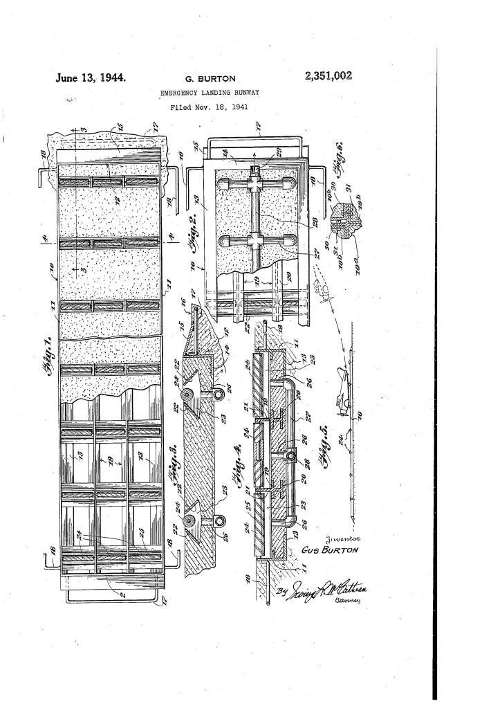
- The Frame (10): A massive steel rectangle with side walls (11) and end walls (12).
- Anchoring Rails (17, 18): These U-shaped rails are welded to the frame and buried deep within the concrete or asphalt (16). This prevents the runway from shifting or “buckling” under the lateral force of a sliding airplane.
- Modular Extensions (30): Burton designed the frames to be bolted together (31) so that a runway could be scaled up to any length or width required for different aircraft sizes.
2. The Spirally Scored Traction Rollers
The “magic” of the runway lies in the rollers (24) that sit slightly above the surface.
- Traction Grooves (25): The rollers are “spirally scored” (like a screw thread or a drill bit). This design helps the roller “grip” the smooth metal of an airplane’s belly, ensuring they begin spinning the instant contact is made.
- Vertical Webbing (21): The rollers are held in place by longitudinal “stringers” (19) that act like the joists in a floor, providing the structural rigidity needed to support a plane’s full weight.
3. Roller-Protecting Pockets and Drainage
A major engineering challenge for a roller-based runway is the weather. If water, mud, or ice collected in the roller mechanisms, they would seize up and become a hazard.
- Diverging Plates (22): Each roller sits in a “pocket” (23) defined by two downwardly-slanted plates. These plates act as a “shroud” to keep debris out of the bearings.
- The Integrated Drain System: Burton designed a network of pipes (26, 27) connecting every pocket to a central longitudinal drain (28). This ensured the rollers remained dry and functional even during heavy rain or snow.
4. The Safety Ramps
To prevent a plane from hitting the edge of the runway like a “curb,” which would tear the fuselage open, Burton added Downwardly Inclined Flanges (15) at both ends.
- Function: These act as “guards” or ramps. If a pilot undershoots the landing, the plane is gently guided “up and onto” the rollers rather than slamming into an abrupt steel abutment.
Comparison Table: Belly Landing Scenarios
| Feature | Standard Concrete Runway | Burton’s Roller Runway |
| Primary Force | High Friction (Sliding). | Rolling Motion (Traction). |
| Heat Generation | Extreme (Fire risk). | Minimal (Rollers dissipate energy). |
| Structural Impact | Fuselage shredding. | Fuselage preservation. |
| Control | High risk of “ground loop.” | Stable linear deceleration. |
| Weather Impact | Hydroplaning risk. | Self-draining (No standing water). |
Significance
Gus Burton’s patent represents an era of “brute force” safety engineering:
- The Carrier Link: The concept of managing high-energy landings in small spaces was a major focus during WWII, paralleling the development of arresting wires on aircraft carriers.
- Civilian Potential: Burton envisioned these for municipal airports to handle emergency landings without shutting down the entire facility for wreckage removal.
- Mechanical Simplicity: Unlike modern “foam bogs” (EMAS) used at the ends of runways today to stop planes, Burton’s system was designed to be reusable—the plane simply rolls to a stop, is towed off, and the runway is ready for the next emergency.
