
Electrostatic Painting (1962)
U.S. Patent No. 3,054,697, granted on September 18, 1962, to Max J. Irland and Allen H. Turner and assigned to the Ford Motor Company, solves a major problem in automotive manufacturing: the uneven deposition of paint on irregular surfaces. While electrostatic painting was already common by 1960, it struggled with “undulating” or nonuniform workpieces.
The Problem: The “Proximity” Effect
In standard electrostatic painting, a high-voltage potential is established between a paint sprayer (charging means) and a grounded workpiece. The paint becomes a charged aerosol that follows the lines of the electric field to the target.
- Declivities and Crests: Electric fields naturally concentrate on the points closest to the source.
- Uneven Coating: In the past, paint would heavily deposit on the “crests” (protrusions) of a car body or part, while “shunning” the declivities (valleys or recessed areas). This resulted in a finish that was too thick in some spots and too thin in others.
The Innovation: The Intermediate Potential Grid
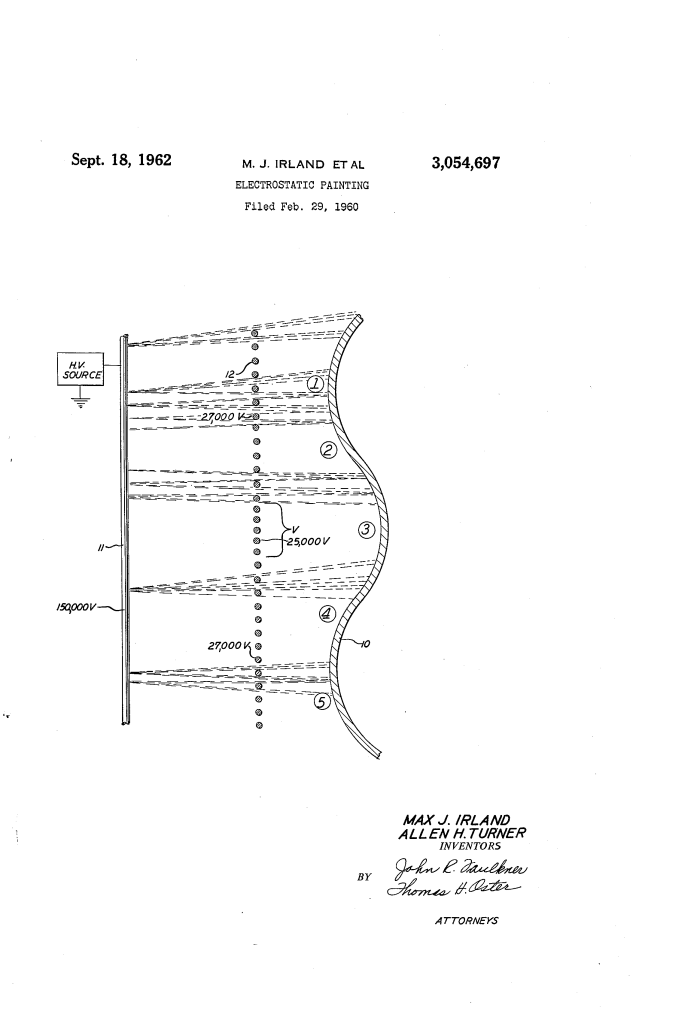
Irland and Turner introduced a system of grid wires (12) interposed between the paint source (11) and the workpiece (10). By charging these wires to specific, nonuniform voltages, they could “steer” the electric field to ensure the aerosol reached the recessed areas.
1. How it Works
The grid acts as a secondary field-shaping tool. By adjusting the voltage on individual wires or sections of the grid, the engineers could neutralize the natural tendency of the paint to rush toward the closest grounded point.
- The Setup: In the patent’s example, the paint sprayer is at -150,000 volts.
- The Grid: A series of wires are placed parallel to the workpiece.
- Dynamic Potential: Wires located closer to the protrusions of the workpiece are charged to a higher potential than those further away. This “pushes” the paint aerosol away from the crests and directs it toward the valleys.
2. Specific Example Parameters
The patent provides a specific test configuration used by Ford:
- Distance: 30 inches between the sprayer and the crests of the workpiece.
- Grid Wires: 31 wires total, spaced 2 inches apart.
- Voltages: The sprayer is at -150,000V. A central group of 5 wires is at -25,000V, while the remaining 26 wires are at -50,000V.
- Result: Testing with patches showed an “approximately uniform” weight of paint across all positions of the undulating surface.
Technical Refinements
The inventors noted several critical operational details:
- Polarity: While the grid wires are usually the same polarity as the sprayer (negative), they can be adjusted or even flipped in polarity depending on the specific geometry of the part.
- Waste Prevention: It is vital to keep a relatively high potential on the grid wires themselves. If the voltage is too low, paint will accumulate on the wires. This could lead to “back-spraying” toward the source or large, uncharged droplets falling and ruining the finish.
- Experimental Evaluation: Because every car part (fenders, doors, hoods) has a unique shape, the patent admits that wire spacing and voltages must be experimentally “tuned” for each specific painting setup.
Significance to the Automotive Industry
Before this invention, complex car parts often required manual “touch-ups” in recessed areas where the electrostatic field failed to reach. By using a shaping grid, Ford could automate the painting of complex surfaces with high precision, reducing paint wastage and ensuring a more durable, uniform finish across the entire vehicle.
