
Electrostatic Paint System (1962)
U.S. Patent No. 3,017,116, granted on January 16, 1962, to R.A. Artman, R.C. Root, and A.H. Turner, describes a sophisticated industrial coating process. While the general concept of using electrostatic force to atomize paint was known at the time, this invention introduced a critical mechanical solution to a common industrial headache: clogging.
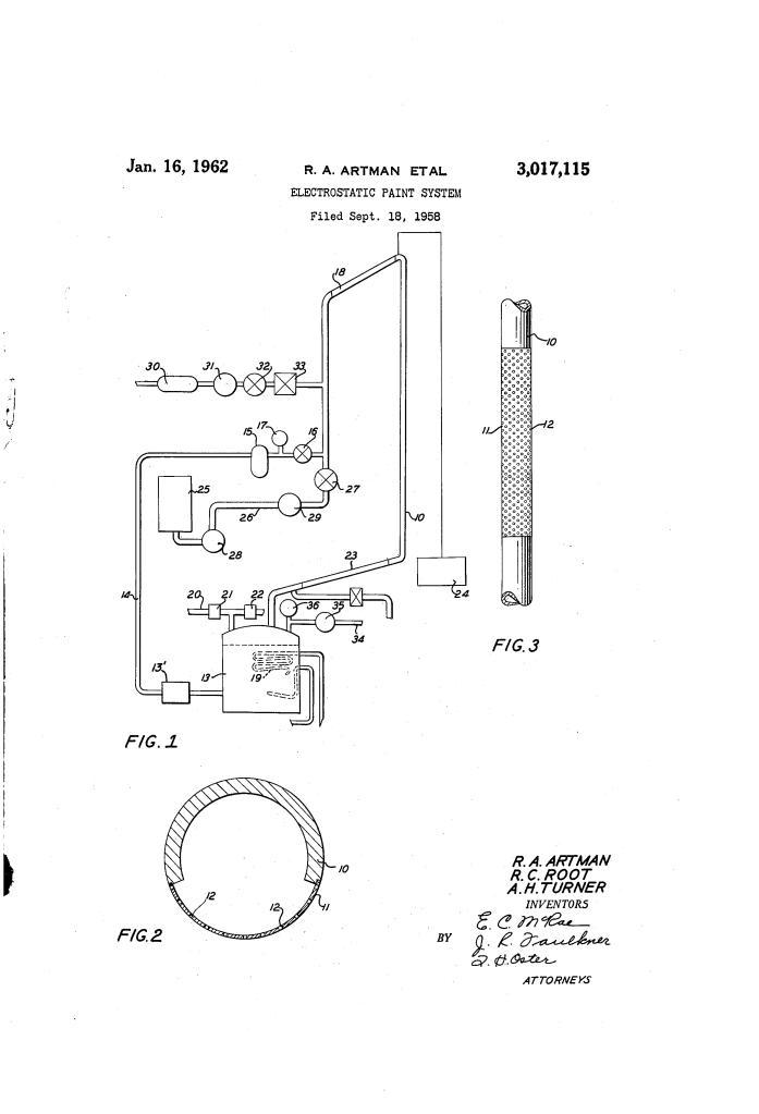
The Innovation: The Self-Cleaning Painting Tube
The primary challenge with early electrostatic systems was that pigments in modern paints (like epoxy-based resins) would quickly “bridge” or plug the tiny orifices required for fine atomization. The Artman system solves this using a two-pronged approach involving pressure balancing and a vacuum cleaning cycle.
1. The Painting Tube (FIG 2 & 3)
The heart of the system is a six-foot-long brass tube.
- Foraminous Sheet (11): A central four-foot section of the tube is replaced with an incredibly thin (0.003 inch) sheet containing 12,000 microscopic holes.
- Micro-Openings (12): Each hole is only 0.003 inch in diameter. This allows for an extremely fine, controlled mist of paint when electrified.
2. The Hydrostatic Pressure Balance
To ensure paint flows evenly out of all 12,000 holes simultaneously, the system must account for gravity.
- Vertical Component: The tube is mounted at an angle or vertically.
- The Physics: The inventors realized that as paint flows down a tube, friction causes a “pressure drop.” By carefully adjusting the paint’s viscosity and flow velocity, they could make the pressure drop perfectly cancel out the increasing weight (hydrostatic head) of the paint. This results in a perfectly uniform internal pressure across the entire four-foot spraying surface.
The “Pulse” Cleaning Cycle
Even with balanced pressure, the tiny holes would eventually plug. The Artman system introduces a Reverse Flow mechanism:
- Painting Phase: For 27 seconds, the system maintains a slight “superatmospheric” (positive) pressure, pushing paint out through the holes where the 100kV electrostatic charge atomizes it toward the grounded workpiece.
- Cleaning Phase: For 3 seconds, a solenoid valve (21) opens to a vacuum source while the atmosphere valve (22) closes.
- The Result: A momentary “subatmospheric” (negative) pressure is created inside the tube. This sucks paint backwards through the 12,000 holes, physically pulling any clogs or pigment bridges back into the main tube to be filtered out.
Technical Specifications & Requirements
| Component | Specification |
| High Voltage Source | At least 100,000 Volts (100 kV) |
| Hole Diameter | 0.003 inch (approx. 76 microns) |
| Paint Viscosity | 1.6 to 2.0 poises |
| Discharge Rate | ~3 gallons of paint per hour |
| Insulation | Polyethylene plastic conduits to isolate the 100kV tube from the pumps |
Industrial Application
This system was designed for repetitious painting of similar objects on an assembly line. By timing the 3-second cleaning cycle to coincide with the gaps between workpieces on a conveyor belt, the system could operate continuously without manual cleaning or downtime.
