

Electronically Scanned Microwave Antennas (1966)
U.S. Patent No. 3,268,901, granted on August 23, 1966, to Frank Reggia and Howard S. Jones, Jr., describes a compact, high-efficiency phased array antenna designed for electronic beam steering without the need for mechanical gimbals or heavy rotating equipment. Assigned to the United States of America as represented by the Secretary of the Army, this invention solved a primary spatial dilemma in phased-array radar design: how to achieve massive differential phase shifts between radiating elements while keeping those radiators packed tightly together to prevent beam degradation.
The Core Problem: The Element Spacing Paradox
To focus radiated microwave energy into a sharp, highly directional beam free of disruptive grating lobes, the radiating elements (slots or dielectric rods) in an array must be spaced extremely close together—typically between one-half and three-quarters of a free-space wavelength.
However, electronically steering that beam over wide angular sweeps requires introducing substantial phase delays between adjacent radiators. Standard inline ferrite phase shifters were physically too long to fit end-to-end within such tight inter-element spacing along a straight waveguide. Earlier designers were forced to compromise: either space the radiators further apart (introducing severe side-lobe distortion) or settle for tiny phase shifts (drastically restricting the beam’s scan angle).
The Innovation: Transverse Folded and Reflection Architectures
Reggia and Jones bypassed this geometry trap through an ingenious topological shift: they moved the phase-shifting elements out of the direct longitudinal path of the waveguide, mounting them perpendicularly to the broad wall of the guide.
By routing the microwave energy into compact, externally folded or reflective channels positioned in the H-plane, they decoupled the physical length of the phase shifters from the physical spacing of the antenna radiators.
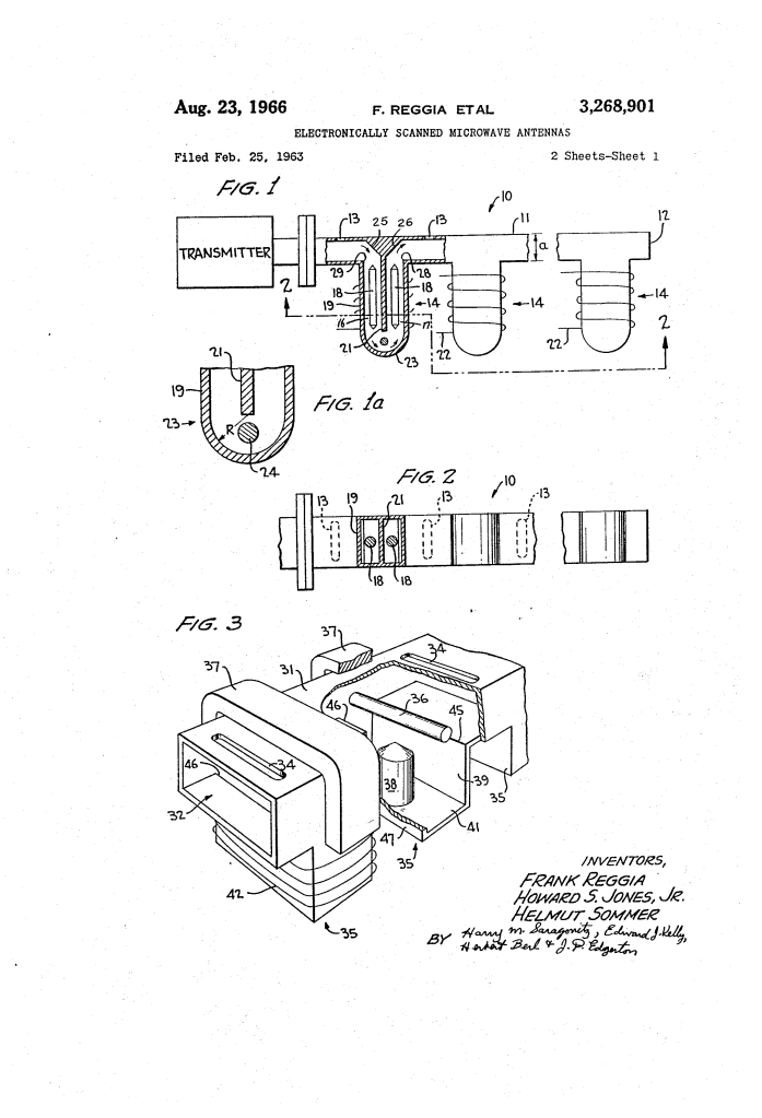
- The Back-to-Back Folded Architecture (FIG. 1 and 2)
- Dual Ferrite Sections (16, 17): Instead of a single long inline tube, two ferrite sections are mounted side-by-side, sharing a common central wall (21).
- Zero-Radius 180-Degree E-Plane Bend (23): Energy enters the first channel via a 90-degree miter bend (25), travels down the first ferrite rod (18), turns sharply around a zero-radius 180-degree bend focused around an impedance-matching pin (24), and travels back up the second channel (17) before returning via a second 90-degree miter bend (26) to the radiating slot (13).
- Double the Phase Shift: This folded path delivers twice the phase delay of a standard section without consuming an additional millimeter of linear space along the antenna array.
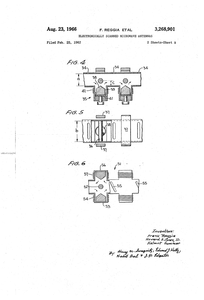
- The Circulator-Coupled Reflection Architecture (FIG. 3, 4, and 5)
- E-Plane T-Junction: A perpendicular stub waveguide (39) forms one branch of a T-junction off the main guide (31).
- Non-Reciprocal Ferrite Circulator (36, 37): A gyromagnetic post (36) magnetized by a permanent magnet (37) sits at the junction, non-reciprocally routing forward-traveling waves into the side stub.
- Short-Circuit Reflection (41): Microwave energy passes through the ferrite rod (38), bounces off an adjustable short-circuit termination (41), and travels back through the rod to the circulator, which directs it forward to the next radiator (34).
- Maximum Efficiency: Because the energy traverses the magnetized ferrite rod twice, the phase shift per unit length is doubled, eliminating one entire impedance-matching taper and dramatically reducing insertion loss.
Technical Components
The system integrates microwave plumbing and solid-state magnetic control:
Waveguide Transmission Line (11, 31): Standard rectangular metallic waveguide (such as RG-52/U for X-band) sized with wide dimension b equal to 0.900 inch and narrow dimension a equal to 0.400 inch, operating in the dominant TE10 mode.
Gyromagnetic Phase-Shifting Rods (18, 38): Coaxially positioned magnesium-manganese (MgMn) ferrite rods situated in asymmetrical waveguide sections held below cutoff in the E-plane to suppress Faraday rotation while concentrating microwave energy inside the core.
Electromagnetic Solenoid Coils (22, 42): Low-power external drive coils wound around each ferrite section to apply variable longitudinal magnetic fields, modulating the phase velocity instantaneously.
Zero-Radius E-Plane Bend Pin (24): A 1/16-inch impedance-matching pin positioned at the apex of the folded guide to prevent destructive internal wave reflections.
Ferrite Circulator Rod (36): A 0.100-inch diameter MgMn ferrite cylinder at the T-junction, biased with an external 2,000-oersted magnetic field to achieve roughly 0.1 dB insertion loss and 25 dB isolation across the 9,300 to 9,400 MHz band.
Radiating Elements (13, 34, 55): Precision transverse slots cut in the broad face (or diagonal slots in the narrow face) spaced at approximately one-half free-space wavelength.
How the Apparatus Functions
The beam-steering process coordinates rapid phase modulation with clean directional transmission:
| Step | Action | Operational Result |
| 1. Launch | Microwave energy from the transmitter travels through the main rectangular waveguide in the dominant TE10 mode. | Power propagates toward the first radiator without initial phase distortion. |
| 2. Redirection | The wave encounters an E-plane 90-degree miter bend (FIG. 1) or a magnetized circulator junction (FIG. 3). | Signal is completely diverted out of the longitudinal path into the perpendicular phase modulator. |
| 3. Phase Delay | Current applied to the electromagnetic drive coils alters the radio-frequency permeability of the ferrite rod. | Modulates the propagation constant, introducing phase delays in excess of 300 degrees per inch. |
| 4. Return | The phase-delayed wave traverses a zero-radius 180-degree bend or reflects off an end-short back through the circulator. | Signal returns cleanly to the main waveguide section immediately upstream of the next radiating slot. |
| 5. Radiation & Scanning | A fractional portion of the phase-delayed wave radiates through the slot; remaining power repeats the process at subsequent stages. | Constructive interference of the radiated wavefronts forms a tight directive beam that scans across space in direct response to the control voltage. |
Performance and Empirical Results
Prototypes built and evaluated at the U.S. Army’s Harry Diamond Laboratories delivered benchmark microwave performance:
- Frequency Range: 9,300 mc to 9,700 mc (X-band operation).
- Phase Modulation Capacity: Surpassed 300 degrees of controllable phase shift per linear inch of ferrite using low applied drive fields.
- Insertion Loss and Isolation: The E-plane circulator setup achieved exceptional efficiency, recording approximately 0.1 dB insertion loss with 25 dB isolation.
- Modulation Purity: Ferrite core dimensioning effectively suppressed Faraday rotation, allowing full-scale continuous beam scanning without unwanted parasitic amplitude modulation.
Historical and Scientific Impact
This patent was instrumental in laying the groundwork for modern solid-state electronically steerable phased-array radars (AESA):
- Elimination of Mechanical Wear: Allowed military and aviation radar to track fast-moving airborne targets nearly instantaneously without bulky, failure-prone motor gimbals.
- Form Factor Revolution: By folding the phase shifters perpendicular to the guide, radar arrays became slim, lightweight, and aerodynamically compatible with advanced aircraft and missiles.
- Bidirectional Utility: The inventors demonstrated that four-port circulator configurations (FIG. 6) allowed the exact same scanning array to function interchangeably as a transmit-receive system.
About the Inventors
Frank Reggia was a seminal microwave physicist at the Harry Diamond Laboratories in Washington, D.C. Widely known for co-inventing the “Reggia-Spencer” phase shifter, his research transformed how electromagnetic waves were modulated inside waveguides, accelerating the development of post-war military radar and electronic countermeasures.
Howard S. Jones, Jr. was an internationally recognized pioneer in radar design, antenna theory, and microwave electronics. Over a celebrated multi-decade career at the Harry Diamond Laboratories, Jones was awarded more than 30 U.S. patents. He became world-renowned for developing conformal antennas—flat, flexible antenna arrays that could be built flush into the skins of rockets, supersonic aircraft, and space exploration vehicles, eliminating aerodynamic drag while surviving intense environmental friction.
Summary of Claims
The patent explicitly claims:
- A beam-scanning microwave antenna comprising a rectangular waveguide with radiating elements spaced along its longitudinal axis and ferrite phase shifters mounted perpendicularly on a broad wall.
- Coupling wave energy into and out of transverse phase shifters via conductive E-plane corners to maintain optimal half-wavelength radiator spacing.
- A phase shifter structure comprising dual asymmetrical waveguide channels connected by a zero-radius 180-degree E-plane bend with an internal impedance-matching pin.
- The integration of an E-plane T-junction with a magnetized gyromagnetic circulator post and a short-circuited reflection-type phase modulator.
- A bidirectional transmit-receive antenna array utilizing dual reflection-type phase modulators coupled through a four-port circulator network.
