
Electrical Resistor (1961)
U.S. Patent No. 2,972,726, granted on February 21, 1961, to Otis F. Boykin, describes a revolutionary method for manufacturing high-precision electrical resistors. Otis Boykin, an African American inventor and engineer, addressed a critical failure in the electronics of the era: traditional resistors were bulky, fragile under extreme conditions, and suffered from unwanted “inductive effects” (interference) caused by the way the wire was wound.
Boykin’s invention provided a resistor that was not only cheaper to produce but also robust enough to withstand the “extreme accelerations and shocks” encountered in rocket flight and high-temperature environments.
The Innovation: The Flat, Flexible Tape Resistance Element
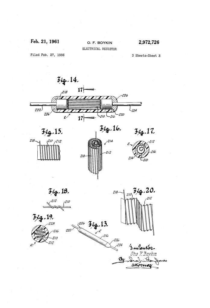
Before Boykin, precision resistors were typically wound around spools or bobbins. This put immense tension on the wire, causing it to stretch and change its resistance. Boykin’s breakthrough was to wind the wire onto a pliable, thin-walled tube which was then flattened into a tape.
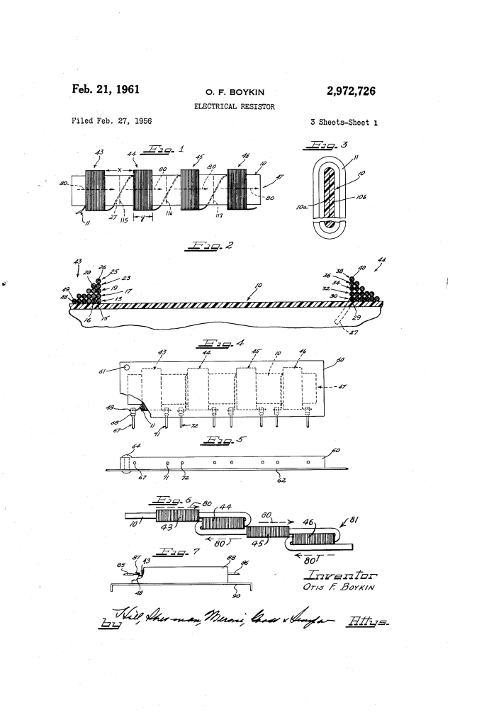
1. The Multi-Layer Winding (Fig. 2)
To save space while maintaining high resistance, Boykin wound the wire in multiple layers.
- The Process: The wire is wound helically in one direction, then the next layer is wound in the opposite direction on top of it.
- The Result: This “criss-cross” or reverse winding technique allows for a massive amount of wire (and thus resistance) to be packed into a very small, flat footprint.
2. Managing Inductance and Capacitance
In electronics, a coil of wire naturally acts as an inductor, which can interfere with high-frequency signals. Boykin solved this through clever folding:
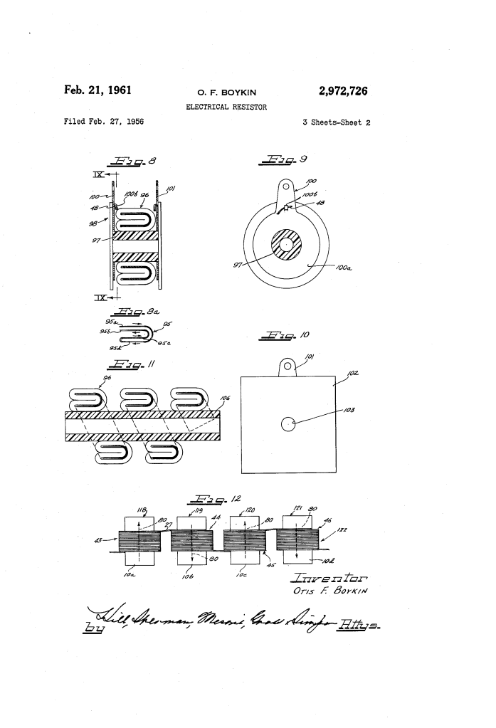
- The “Accordion” or Pleated Fold (Figs. 6 & 20): By folding the resistance tape back and forth, the magnetic fields of adjacent sections oppose and cancel each other out.
- The Result: A resistor that is “non-inductive,” making it perfect for precise scientific instruments and computers.
Construction and Materials
The patent details specific materials and methods that made the Boykin resistor superior for industrial and military use:
| Feature | Boykin’s Design | Benefit |
| Core Material (10) | Polyethylene or Glass Fiber tube | Pliable and soft; allows for expansion/contraction without snapping the fine wire. |
| Encapsulation (60) | Epoxy Resin Case | Protects against moisture (corrosion) and makes the unit shockproof. |
| Terminal Hook (68) | Mechanically clamped hook | Avoids soldering or brazing, which can make the fine resistance wire brittle and prone to breaking. |
| Mounting | Flat extended surface contact | Maximizes heat dissipation by allowing the resistor to lie flat against a chassis. |
About the Inventor: Otis F. Boykin
Otis Boykin (1920–1982) was a prolific inventor with over 25 patents. His work in resistor technology had a profound impact on several fields:
- The Heart Pacemaker: A version of his resistor was used in the first implantable pacemaker, providing the precise electrical control necessary to regulate a human heartbeat.
- Military and Aerospace: His resistors were utilized in guided missiles and IBM computers because they could maintain accuracy despite extreme temperature swings and vibrations.
- Consumer Goods: He also invented various “control units” for household appliances, making electronics more reliable and affordable for the general public.
Summary of Claims
The patent claims cover:
- A method of making a resistor by winding wire on a tube and then flattening it into a tape.
- The V-shaped or U-shaped longitudinal folding of the tape to reduce space.
- The use of spaced groups of turns to manage potential differences and minimize capacitive effects.
- The specific mechanical terminal connection that eliminates wire-weakening heat treatments.
