
Electro-Motive Railway (Granville T. Woods, No. 385,034)
The patent by Granville T. Woods of Cincinnati, Ohio, describes a comprehensive system for an Electro-Motive Railway (Patent No. 385,034, 1888). This invention represents a significant leap in the electrification of urban transit, moving beyond simple “power lines” to a sophisticated block-signaling and power-distribution system. Woods’s primary objective was to create a safer, more efficient way to power multiple locomotives on the same line, ensuring that they could be operated in series without the danger of short-circuiting or catastrophic power loss.
Inventor Background: Granville T. Woods
Granville T. Woods (1856–1910) was a prolific African American inventor often referred to as “The Black Edison.” His 1888 patent for the Electro-Motive Railway addressed the most complex problem of early electric rail: how to manage electricity across miles of track with moving vehicles. Woods was a master of electrical logic and circuit design; his “block system” is a foundational concept in railway safety that is still used globally to prevent train collisions by dividing tracks into independent, monitored sections.
Key Mechanical & Electrical Components
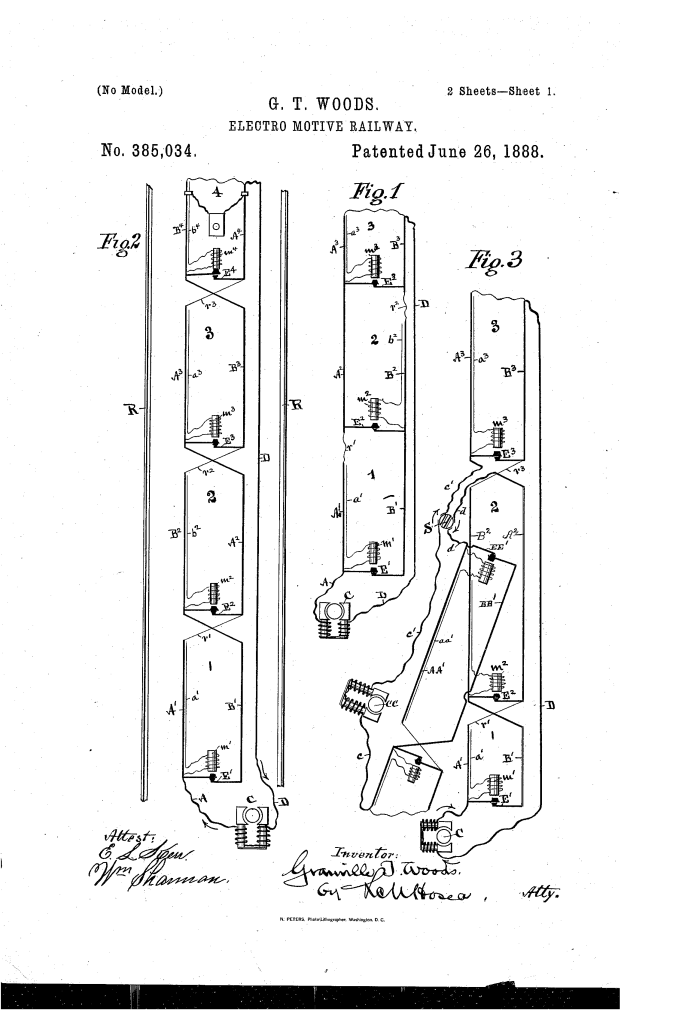
The system consists of a dual-branch conductor housed in an underground conduit, governed by automatic magnetic shunts.
1. The Dual Branch Outgoing Conductor (A, B)
- Divided Polarity: The outgoing power line is split into two parallel branches, A and B.
- The Block System: The track is divided into “blocks” (1, 2, 3, etc.). In each block, one branch has a high resistance (r) while the other is unrestricted.
- Function: As the locomotive moves, its brushes bridge across branches A and B. This creates a “potential difference,” shunting power through the motor to propel the car.
2. The Automatic Magnetic Switch (E, m)
- The Switch (E): A transverse contact switch that connects branches A and B at the start of each block.
- The Magnet (m): An electro-magnet that holds the switch open when energized.
- Function: When a locomotive enters a block, its brushes close a small auxiliary circuit (a, b), energizing the magnet and opening the switch. This forces the current to flow through the locomotive rather than across the switch, effectively putting the train in series with the power line.
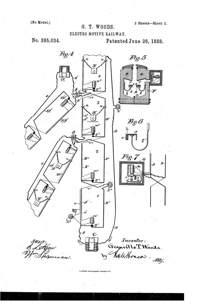
3. The Sub-Surface Conduit (F)
- Weather Protection: The conductors are housed in a wooden or insulated conduit (F) beneath the roadway.
- Water Management: The conduit features an overhanging roof (f) and a central slot designed to shed water away from the electrical components.
- Supporting Brackets (g): The copper conductors are held by insulated brackets deep within the sheltered sides of the conduit.
4. The Rubbing-Contact Shunt (i, j, k) (Key Innovation)
- Armature (i): The shunt magnet features an armature with a sliding finger (j).
- Self-Cleaning Action: Every time the magnet actuates, the finger rubs against the contact piece (k).
- Function: This “rubbing friction” clears away any oxidation or debris, ensuring a perfect electrical contact that actually improves with use.
System Capabilities: Side Tracks and Lighting
Woods’s system was designed for the practical complexity of a real-world city.
- Independent Side Tracks: The patent includes diagrams for side-track systems (Fig. 3) that can be looped into the main line or powered by an auxiliary generator (CC) for heavy gradients (steep hills).
- Auxiliary Lighting: The motor current can be utilized to power incandescent lamps (L) or signal bells at junctions and bridges.
- Series Operation: Because the locomotives act as moving substitutes for the block switches, multiple trains can occupy the line, each drawing its required power in a sequence (series) rather than competing for a single shared load.
Improvements Over Previous Electric Railways
| Feature | Standard 1880s Rail Systems | Woods’s Electro-Motive Railway |
| Circuit Safety | Open wires were prone to sparking/static. | Normally-closed switches and continuous conductors prevent sparking. |
| Power Management | Hard to manage multiple trains on one line. | Block-system allows locomotives to operate in series safely. |
| Weather Resistance | Exposed wires failed in rain/snow. | Sheltered conduit (F) with integrated water-shedding roof. |
| Contact Reliability | Brushes often lost contact or corroded. | Rubbing-contact shunts improve electrical connection through use. |
Significance to Electrical Engineering
Granville T. Woods’s railway system influenced the development of automated transit and industrial control systems.
- The Block System: Woods helped pioneer the logic that a train should “own” its section of track electrically, a principle that evolved into the Automatic Train Control (ATC) used in modern subways.
- Integrated Infrastructure: By housing the power, the return line, and the signal circuits in a single underground conduit, Woods anticipated the multi-utility tunnels used in modern urban planning.
- Contact Friction Logic: The idea that mechanical friction should be used to clean electrical contacts (the rubbing finger) is a standard design feature in high-voltage switchgear today.
- Fail-Safe Continuous Loops: By keeping the conductors “unbroken” even if a motor fails, Woods ensured that a single broken car wouldn’t kill the power for the entire city line.
