
Electro-Mechanical Brake (Granville T. Woods, No. 368,265)
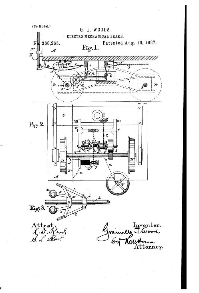
The patent by Granville T. Woods of Cincinnati, Ohio, describes an Electro-Mechanical Brake (Patent No. 368,265, 1887). This invention represents a significant leap in railway safety and automation. Woods’s primary objective was to create a braking system that used the rotation of the car’s axle as its power source, but utilized an electric current to control when the brakes were applied. Most notably, the system was designed to be “normally active,” meaning the brakes would engage automatically if power failed or was cut, providing an early form of fail-safe protection.
Inventor Background: Granville T. Woods
Granville T. Woods (1856–1910) was a legendary African American inventor known for his mastery of electricity and mechanical engineering. This 1887 patent addressed one of the most dangerous aspects of 19th-century railroading: the inability to stop heavy trains quickly and reliably. By integrating a centrifugal governor and an electric motor control, Woods moved away from manual hand-brakes toward an automated, speed-responsive system. His designs were so effective that they laid the groundwork for the modern braking systems used in subways and high-speed rail today.
Key Mechanical Components & Functions
The system uses the car’s movement to power the brakes, with an electrical “hold-off” mechanism.
1. The Swinging Frame and Friction Gear (c, b, e)
- Axle Power: A friction gear (e) is fixed to the car-axle (a).
- The Frame: A swinging frame (c) is pivoted to the car’s truck and carries a counter-shaft (d) with its own friction gear (b).
- Gravity Engagement: By default, gravity causes the frame to swing downward, bringing gear (b) into contact with gear (e). As the car moves, the axle rotates the counter-shaft.
2. The Winding Drum and Friction Disks (f, h)
- Winding Drum (f): Loose on the counter-shaft is a drum that winds the brake-chain (g).
- Clamping Surfaces: The drum is sandwiched between a fixed disk and a sliding friction disk (h).
- The Spring (s): A coiled spring (s) normally pushes the disk (h) against the drum.
- Function: This friction causes the rotating shaft to turn the drum, winding the chain and pulling the brakes against the wheels.
3. The Centrifugal Governor (k, w, i) (Key Innovation)
Woods integrated a steam-engine style governor to make the braking force responsive to the car’s speed.
- Weights (w): As the counter-shaft spins, weights (w) move outward due to centrifugal force.
- Automatic Pressure: This movement pushes the sliding collar (i), which compresses the spring (s) even further.
- Function (Speed Control): The faster the car moves, the harder the governor clamps the drum, and the more force is applied to the brakes.
- Function (Anti-Skid): If the wheels lock up and stop rotating (“skid”), the governor stops spinning. The spring pressure immediately drops to its minimum, loosening the brakes just enough to let the wheels start turning again.
4. The Electric Control Motor (D)
This is the “Electro” part of the electro-mechanical brake.
- The Motor (D): An electric motor is mounted to the car body.
- The Suspension Chain (r): This motor winds a chain (r) that lifts the swinging frame (c) upward.
- Action: When the operator applies electricity to the motor, it lifts the frame, pulling the gears (b and e) apart. The braking apparatus becomes inert.
- Braking: To stop the car, the operator cuts the power to the motor. The frame drops, the gears engage, and the mechanical system takes over to stop the train.
Improvements Over Standard Railway Brakes
| Feature | Manual Hand-Brakes | Woods’s Electro-Mechanical Brake |
| Braking Force | Limited by the physical strength of the brakeman. | Powered by the car’s own momentum (Axle-driven). |
| Responsiveness | Slow; required manual coordination across cars. | Automatic engagement when the electric circuit is broken. |
| Speed Adaptation | Uniform pressure regardless of speed. | Governor (k) increases pressure at high speeds for better stopping. |
| Wheel Protection | Prone to locking wheels and causing flat spots. | Governor naturally releases pressure if wheels stop rotating (Early ABS). |
Significance to Engineering and Safety
Granville T. Woods’s electro-mechanical brake influenced the development of automated transit and fail-safe systems.
- Fail-Safe Logic: By designing the brakes to be held off by electricity and applied by gravity/springs, Woods ensured that if a train car became uncoupled or lost power, it would automatically stop itself.
- Early Anti-Lock Braking (ABS): The use of the centrifugal governor to modulate braking force based on wheel rotation is a direct conceptual ancestor to modern ABS systems.
- Centralized Control: His design allowed a single engineer to control the brakes of an entire train from the locomotive by simply managing a single electrical circuit.
- Part Longevity: Woods specifically designed the mechanism to remain “inert when not directly in use” to prevent unnecessary wear on the rotating parts while the train was cruising.
